
User's Manual


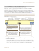


Table Of Contents
Deployment Guide 127
EXAMPLE 9: CREATING WLAN POLICIES
1. Click Configuration > WLAN Policies > New, enter the following on the first page of the new WLAN policy
dialog box:
• Name: WLANpolicy-1 (You cannot use spaces in the WLAN policy name.)
• Description: Enter a useful description, such as "HiveAPs in Bldg1 at HQ".
Network Settings
2. Enter the following in the Network Settings section. (Note that the hive and VLAN were previously
configured in "Example 8: Creating Hives" on page 125 and "Defining VLANs" on page 100.)
•Hive: Hive1
•MGT Interface VLAN: 1 (or VLAN-1-EmployeeData)
In this example, the MGT interface is in VLAN 1, the same VLAN as that for employee data traffic. You
can specify either the predefined VLAN "1" or "VLAN-1-EmployeeData", which was previously created.
• MGT IP Filter: leave empty. A management IP address filter defines addresses from which admins are
permitted administrative access to HiveAPs. This filter was not configured in the preceding examples.
Service Settings
3. Leave the Service Settings fields at their default values or empty. None of these options were modified or
configured in the preceding examples.
Management Server Assignment
4. Enter the following in the Management Server Assignment section. (Note that the following settings were
previously configured in "Example 6: Setting Management Service Parameters" on page 120 and "Example 7:
Defining AAA RADIUS Settings" on page 123.)
•DNS Server: DNS-Servers
• Syslog Server: Syslog-Server
•SNMP Server: SNMP-Server
• Time Settings: NTP-Server
• RADIUS Server: RADIUS-Servers
• Location Server: None available (this option was not configured in the preceding examples)
5. To proceed to the next page, click Next.