
User Manual

A
SCALE 1 : 5
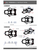
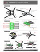
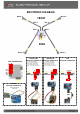
STEP 06
A
MOTOR WIRES GO FROM
ESC THROUGH CF TUBES
N
DETAIL N
SCALE 2 : 3
SOLDER BEC WIRES TO PCB
B
ESC 1
ESC 2
ESC 3
ESC 4
BEC
ESC 1 ESC 2
ESC 4
B
ESC 3
SCALE 1 : 4
Button Screw M3x5mm
13 pcs ( BHS3005 )
Button Screw M3x12mm
8 pcs ( BHS3012 )
The bolts are actually black
Top Frame
1 pcs ( 3D-002 )
SCALE 1 : 6
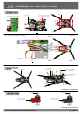
STEP 07
SCALE 1 : 2
MOTORS
MOTORS
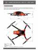
- Main rotor diameter: 458mm (with 06 inch propellers)
- Propeller length: 06 inch
- Weight including standard electronics: 4000g (excluding
batteries).
- Battery compartment: 2200mAh
Chapter 07 – Arm system assembly, Clamp systems assembly,
GPS system assembly
Chapter 08 – Frame upper system assembly, Frame lower
system assembly, Llink of sprayer system.
Chapter 09 – Assembling the Groups
Chapter 10 – .................
INDEX
Chapter 01 – Specifications
Chapter 02 – Important notes
Chapter 03 – In the Box
Chapter 04 – Landing gear systems assembly
Chapter 05 – Sprayer systems assembly
Chapter 06 – Electronic tray assembly, Pump
system assembly, Battery tray assembly.
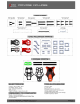
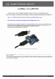
CARBON FLAST - RUBBER - POWER DISTRIBUTION BOARD
Motors: DYS BE1806
Propeller: 6 Inch, 4 pcs
ESC:
Battery: 3S 2200mah
Flight Controller
Camera
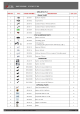
CNC PARTS
ALL PARTS
SUGGESTED SOMPONENTS
To use the loctite 243 on the bolts metal
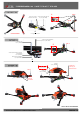
FINISHED ASSEMBLY
Note:
Cameras will be assembled this
location when we finished the kit
To use the loctite 243 on the bolts metal
Use Loctite on all metal bolts
Carbon Tube 14x16x129mm
2 pcs ( 3D-010 )
30A Reversible ESC
4 pcs ( 3D-017 )
Power Distribution Board
1 pcs ( 3D-019 )
Nylon screw M3x12
and Nylon nut M3
( four couples )
STEP 05
STEP 04
FINISHED ASSEMBLY
Spacer 12mm
4 pcs ( 3D-025 )
Button Screw M3x18mm
( BHS-3018 )
MOTOR WIRES GO FROM
ESC THROUGH CF TUBES
BEC 5V-3A
Note: Be careful to correctly plug the ESC and
BEC wires into the flight controller.
Button Screw M3x5mm
13 pcs ( BHS3005 )
Button Screw M3x12mm
8 pcs ( BHS3012 )
Red-Motor mount
2 pcs ( 3D-004 )
Black-Motor mount
2 pcs ( 3D-004 )