
Technical data


INSTALLATION, OPERATION & MAINTENANCE
7-2
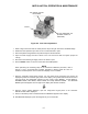
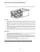
7. Remove the “E” screws on the two sides of
the burner manifold.
8. Remove the sheet metal protections “F” on
the two sides of the burner manifold.
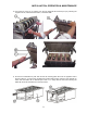
9. Position the burner manifold, at the two sides, 3/8” (10 mm) higher than the standard position
shown below. It is possible to achieve this by positioning the tapped hole of the gas pipe flange
relative to the “G” hole of the side support and inserting one of the two screws “E” previously
removed (see following pictures and drawing).