Instruction No. GF-115H AERCO INTERNATIONAL, Inc., Northvale, New Jersey, 07647 USA Installation, Operation & Maintenance Instructions Gas Fired Boiler Systems Modular, Condensing, Hot Water Boilers Models: 303, 454, 606, 757, 909, 1060 Printed in U.S.A.
Telephone Support Direct to AERCO Technical Support (8 to 5 pm EST, Mon. – Fri.) 1-800- 526-0288 The information contained in this manual is subject to change without notice from AERCO International, Inc. AERCO makes no warranty of any kind with respect to this material, including but not limited to implied warranties of merchantability and fitness for a particular application. AERCO International is not liable for errors appearing in AERCO International, Inc. 159 Paris Avenue Northvale, NJ 07647-0128 www.
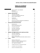
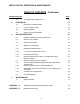
INSTALLATION, OPERATION & MAINTENANCE TABLE OF CONTENTS Chapter/Paragraph 1 2 3 4 Page SAFETY SYMBOLS AND WARNINGS iii IMPORTANT iii FOR YOUR SAFETY v GENERAL DESCRIPTION 1-1 1.1 TECHNICAL FEATURES 1-1 1.2 CODES AND STANDARDS APPROVALS 1-2 1.3 INSTALLATION FLEXIBILITY 1-2 1.4 DIMENSIONS 1-3 1.5 TECHNICAL DATA 1-5 1.6 MODULEX SIDE VIEW SHOWING MAIN COMPONENTS 1-6 1.7 BOILER FREEZE PROTECTION 1-7 INSTRUCTIONS FOR INSTALLERS 2-1 2.1 INTRODUCTION 2-1 2.
INSTALLATION, OPERATION & MAINTENANCE TABLE OF CONTENTS - Continued Chapter/Paragraph 4.8 5 6 GAS MAINS AND CONNECTION 4-3 ELECTRICAL 5-1 5.1 ELECTRICAL CONNECTIONS 5-1 5.2 D.H.W. STORAGE TANK 5-2 5.3 ENABLE/DISABLE 5-2 5.4 INSTALLATION OF SENSORS 5-2 BOILER OPERATION 6-1 6.1 GENERAL DESCRIPTION AND OPERATION 6-1 6.2 MODULATION THEORY 6-1 6.3 IGNITION SEQUENCE 6-2 6.4 MODES OF OPERATION 6-2 6.4.1 INDOOR/OUTDOOR RESET 6-2 6.4.2 0 TO 10 VOLT REMOTE SET-POINT 6-3 6.4.
INSTALLATION, OPERATION & MAINTENANCE SAFETY SYMBOLS The following defined symbols are used throughout this manual to notify the reader of potential hazards of varying risk levels. INDICATES AN IMMINENTLY HAZARDOUS SITUATION, WHICH IF NOT AVOIDED, WILL RESULT IN DEATH OR SERIOUS INJURY. INDICATES A POTENTIALLY HAZARDOUS SITUATION, WHICH AVOIDED, COULD RESULT IN DEATH OR SERIOUS INJURY. IF NOT INDICATES A POTENTIAL HAZARDOUS SITUATION, WHICH IF NOT AVOIDED, MAY RESULT IN MINOR OR MODERATE INJURY.
INSTALLATION, OPERATION & MAINTENANCE WARNINGS CONTINUED • This INSTRUCTION MANUAL is an integral and indispensable part of the product. It must be given to the user by the installers and must be kept in a safe place for future reference. In the event that the boiler is transferred or sold, the manual must accompany the equipment. • This boiler must be used only for the purposes for which it has been designed.
INSTALLATION, OPERATION & MAINTENANCE FOR YOUR SAFETY For boilers that use gaseous fuel, what to do if you smell gas. • • • • Do not try to light any appliance. Do not touch any electric switch; do not use any phone in your building. Immediately call your gas supplier from a neighbor’s phone. Follow the gas supplier’s instructions. If you cannot reach your gas supplier, call the fire department. NEVER USE FLAMES TO DETECT GAS LEAKS.
INSTALLATION, OPERATION & MAINTENANCE Extracted Information From 248 CMR 5.08 (2) – Continued a. In the event that the side wall horizontally vented gas fueled equipment is installed in a crawl space or an attic, the hard wired carbon monoxide detector with alarm and battery back-up may be installed on the next adjacent floor level. b.
INSTALLATION, OPERATION & MAINTENANCE 1 GENERAL DESCRIPTION IMPORTANT Each AERCO Modulex Boiler is shipped as either a Natural Gas Only Boiler OR a Propane Gas Only Boiler. It Is Not a Dual-Fuel Boiler. Ensure that the correct fuel and fuel pressure are used when operating the equipment. 1.1 – TECHNICAL FEATURES Modulex is a compact, modular, gas fired, Low NOx, condensing boiler. The boiler body, is comprised of sections of cast aluminum/magnesium/silicon alloy.
INSTALLATION, OPERATION & MAINTENANCE 1.2 - CODE AND STANDARDS APPROVALS MODULEX has been reviewed for compliance with the applicable sections of the following North American Standards: Z21.13: ASME SECTION IV: BTS 2000: SCAQMD Rule 1146.
INSTALLATION, OPERATION & MAINTENANCE 1.4 DIMENSIONS AND WEIGHTS The dimensions and weights for each Modulex Model are shown in sheets 1 and 2 of Figure 1-1. Figure 1-1.
INSTALLATION, OPERATION & MAINTENANCE Figure 1-1.
INSTALLATION, OPERATION & MAINTENANCE 1.5 - TECHNICAL DATA (THE NAME PLATE IS PLACED UNDER THE FRONT JACKET NEXT TO THE CONTROL PANEL.
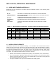
INSTALLATION, OPERATION & MAINTENANCE SPECIFICATIONS: (continued) Model Number MLX-303 MLX-454 MLX-606 MLX-757 MLX-909 Water Pressure Drop @ Max. Flow 5 psi (34.5 kPa) 6 psi (41.4 kPa) 9 psi (62.1 kPa) 10 psi (68.9 kPa) 13 psi 15 psi (89.6 kPa) (103.4 kPa) Water Volume: Gallons 2.8 3.8 4.9 5.9 6.9 8.0 Water Volume: Liters 10.4 14.4 18.4 22.3 26.3 30.
INSTALLATION, OPERATION & MAINTENANCE FAN GAS VALVE AIR INTAKE CONNECTION GAS PIPE AUTOMATIC AIR VENT BURNER COVER IGNITION FLAME DETECTOR LOCAL NTC SENSOR GLOBAL FLOW NTC TEMPERATURE SENSOR H.L. THERMOSTAT BURNER HOT WATER OUTLET (SUPPLY) ALUMINUM/ SILICON HEAT EXCHANGER 1/4" CONNECTION WITH PLUG GLOBAL RETURN NTC TEMPERATURE SENSOR BOILER FRAME COLD WATER INLET (RETURN) WATER DRAIN VALVE CONDENSATE DRAIN TRAP CONDENSATE COLLECTION TRAY MANIFOLD FILLING-UP ELBOW 5.
INSTALLATION, OPERATION & MAINTENANCE 2 INSTRUCTIONS FOR INSTALLERS 2.1 INTRODUCTION The Modulex Boiler is intended to be installed as a Category IV vent installation and must be installed in compliance with all applicable laws and regulations including the ones below. See section 3.1 for Category descriptions.
INSTALLATION, OPERATION & MAINTENANCE Packed inside the boiler packing you will find: • Painted steel panels: • The front one connected to the back panel by a shrink wrap film • The right hand side panel connected to the left hand panel by shrink wrap On the front of the boiler: • Flue collector, with exhaust connector screwed to the pallet: 6 inch for models 303 to 606 and 8 inch for models 757 to 1060.
INSTALLATION, OPERATION & MAINTENANCE 2.2.2 Locating the Boiler The boiler should be located on a level, solid area or base as near to the outside wall as possible and centrally located to the space heating distribution system. Special attention must be given to local regulations and codes about boiler rooms and particularly to the maintaining of minimum clearances and empty space around the boiler.
INSTALLATION, OPERATION & MAINTENANCE 2.2.4 Boiler Connections Upon delivery, the Modulex Boiler has all the connections on its R.H. side (Figure 2-3). Note that the R.H. orientation is the right hand side when viewed facing the front of the boiler. These connections include: water supply and return, gas, combustion air intake and flue collector outlet.
INSTALLATION, OPERATION & MAINTENANCE BCM TEMP SENSOR AUTOMATIC AIR VENT E8 TEMP SENSOR RETURN TEMP SENSOR BOILER DRAIN THERMOWELL THERMOWELL CLIP SENSOR BRACKET SENSOR CONNECTOR BRACKET SCREW E8 TEMP SENSOR TEMPERATURE SENSOR E8 SENSOR BCM & BOILER RETURN SENSORS Figure 2-4 Right Hand (R.H.
INSTALLATION, OPERATION & MAINTENANCE 3. Disassemble the flow (supply) and return manifolds (Figure 2-5), leaving the rubber gaskets in place on the upper holes of the aluminum sections and the rubber gaskets/diaphragms in place on the lower holes. The diaphragms on the end sections have a hole diameter of .866 in. (22 mm). 4. Reassemble the manifolds with the threaded connection on the opposite side as shown in Figure 2-5. Change the position of the drain cock and the automatic air vent (Figure 2-6). 5.
INSTALLATION, OPERATION & MAINTENANCE AUTOMATIC AIR VENT BCM TEMP SENSOR E8 TEMP SENSOR RETURN TEMP SENSOR BOILER DRAIN THERMOWELL THERMOWELL CLIP SENSOR BRACKET SENSOR CONNECTOR BRACKET SCREW E8 TEMP SENSOR TEMPERATURE SENSOR E8 SENSOR BCM & BOILER RETURN SENSORS Figure 2-6 Left Hand (L.H.
INSTALLATION, OPERATION & MAINTENANCE 6. For the gas connection, it is possible to keep the gas manifold inlet on the R.H. side, if desired, or it can be rotated 180° to have it on the L.H. side. In case of reversal from R.H. side to L.H. side of the gas manifold, only on the Modulex Model 303 will it be necessary to reverse plug C with the gas valve fitting A (see gas manifold connections in Figure 2-5).
INSTALLATION, OPERATION & MAINTENANCE Figure 2-7 Sample Data Plate 2-9
INSTALLATION, OPERATION & MAINTENANCE Table 2-1. Modulex Data Plate Entries MODEL NUMBER REVISION TYPE OF GAS *SERIAL NO.
INSTALLATION, OPERATION & MAINTENANCE 3 GENERAL INFORMATION FOR VENTING Note: See Venting Guide GF-115-V for venting specifications and materials. 3.1 VENT PIPE CONNECTION The Modulex boiler is approved for a Category IV vent configuration as well as for sealed combustion installations. Provisions for combustion and ventilation air in accordance with section 5.3, Air for Combustion and Ventilation, of the National Fuel Gas code, ANSI Z223.1, or Sections 7.2, 7.3, or 7.
INSTALLATION, OPERATION & MAINTENANCE Pipe lengths and fittings must be calculated as part of the equivalent length. The pressure drop of the vent and combustion air systems must not exceed 100 equivalent feet each. Note that this DOES NOT mean the allowed combined pressure drop between the vent and combustion air is 200 equivalent feet. That is, the vent cannot go above 100 equivalent feet, even if the combustion air is less than 100 equivalent feet, and vice versa.
4 PIPING NOTE: For in depth piping information for the boiler, see Piping Guide GF-115-P-H 4.1 MAKEUP WATER QUALITY Water at the installation should be checked, monitored, maintained and treated as described in GF-115-P-H. NOTE: Failure of the boiler due to water quality is not covered under warranty. 4.2 - MAXIMUM ALLOWABLE WORKING PRESSURE The Modulex boiler has a maximum allowable working pressure of 92 psi (634kPa, 6.34 bar), and a minimum of 15 psi (103 kPa, 1 bar). 4.
INSTALLATION, OPERATION & MAINTENANCE 4.6 SYSTEM FILLING & DRAINING • For filling-up the system a filling tap has to be inserted on the system return pipe. • The filling-up can also be made through the draining tap on the boiler return manifold. • In both cases, an approved hydraulic disconnection system has to be fitted. • Before connecting the boiler, carefully rinse out the whole system with running water. 4.
INSTALLATION, OPERATION & MAINTENANCE 5 ELECTRICAL NOTE: For additional electrical information, see Electrical Power Guide GF-115-E 5.1 ELECTRICAL CONNECTIONS A complete electrical wiring diagram for the Modulex is provided under separate cover in the manual package. For electrical ratings, refer to the technical data in paragraph 1.5. The boiler installation requires a 120 VAC, 60 Hz – single-phase power input. The electrical connections must conform to local and NEC or CEC requirements.
INSTALLATION, OPERATION & MAINTENANCE 5. It is necessary to install a double-pole switch on the supply line in an easily accessible position in order to quickly and safely disconnect service. Do Not affix switch to boiler sheet metal enclosure. Figure 5-1. Junction Box Wiring Connections After placing the boiler in operation, the ignition system safety shutoff device must be tested.
INSTALLATION, OPERATION & MAINTENANCE Figure 5-2.
INSTALLATION, OPERATION & MAINTENANCE 6 BOILER OPERATION 6.1 GENERAL DESCRIPTION AND OPERATION The Modulex is a cast aluminum body boiler consisting of mutually connected combustion chambers, each having its own burner, blower and air pressure switch, gas valve, ignitor and flame detection. Each group of these components is referred to as a module.
INSTALLATION, OPERATION & MAINTENANCE 6.3 IGNITION SEQUENCE The ignition sequence is described below and shown in the following diagram (Figure 6-1). The Ignition Burner Management Module (BMM) is powered on and, after 5 seconds the fan starts at minimum speed. The fan remains running, actuating the air pressure switch and pre-purging the combustion chamber for 10 seconds. Actuating the air pressure switch toggles it from normally open (NO) to normally closed (NC).
INSTALLATION, OPERATION & MAINTENANCE The outside air sensor, supplied with the boiler, should be mounted on an outer North or Northeast, wall at a minimum height from floor of 8 feet, 2.5 inches (2.5 m) away from windows, doors and ventilation grates. Never mount the outside air sensor in a sunny position. The connections for the sensor are at connector number 1, terminals 9 (F9) and 10 (GND) of the boiler controller. 6.4.
INSTALLATION, OPERATION & MAINTENANCE 6.5.1 Tools and Instrumentation Required For Combustion Calibration The following tools and instrumentation are necessary to perform combustion calibration of the unit: • Digital Combustion Analyzer: Oxygen (O2) and Carbon Dioxide (CO2) accuracy to ±0.4%; Carbon Monoxide (CO) resolution to 1 ppm • One 16” W.C. manometer or equivalent gauge • Small and large flat-tip screwdrivers • T40 Torx tool • Length of plastic tubing (3/8” I.D.) 6.5.
INSTALLATION, OPERATION & MAINTENANCE 6.5.3 Preparing The Flue For Use With The Combustion Analyzer In order to provide an opening for the combustion analyzer, proceed as follows: 1. Drill a 3/8” hole in the PVC vent pipe, approximately 2 feet above the boiler exhaust manifold. 2. If necessary, adjust the stop on the combustion analyser probe so that it will extend mid-way into the flue gas flow. DO NOT install the probe at this time. 6.5.
INSTALLATION, OPERATION & MAINTENANCE NOTE The CASCADE MANU (Cascade Manual) mode will time out after a period of 15 minutes. When this occurs, the boiler will revert the Auto mode function under program control. 9. Turn the Rotary Knob clockwise until CASCADE MANU is displayed. 10. Press the Program Key. BOILER 1 will be displayed. 11. Press the Program Key again. The display will show CODE NO., requesting the valid code to be entered. 12. Enter code 0000 (4 zeros) by pressing the Program Key four times.
INSTALLATION, OPERATION & MAINTENANCE CAP SCREW / OFFSET ADJUSTMENT OUTLET OUTLET PRESSURE TAP (NORMAL MANIFOLD PRESSURE) Figure 6-2. Gas Valve Adjustment 1. Refer to Figure 6-2 and locate the outlet pressure tap for the gas valve of the first Boiler Stage. 2. Rotate the outlet pressure tap screw 1/2 turn counterclockwise to open. 3. Attach the plastic tubing between the pressure tap and the manometer. 4. Open the water supply and return valves to the unit and ensure that the system pumps are running.
INSTALLATION, OPERATION & MAINTENANCE NOTE The CASCADE MANU (Cascade Manual) mode will time out after a period of 15 minutes. When this occurs, the boiler will revert the Auto mode and will function under program control. If this occurs prior to completing the combustion calibration for each Boiler stage, it will be necessary to repeat steps 7 through 15 and then sequence the Boiler stage to the one which was in-process when the time out occurred. 11.
INSTALLATION, OPERATION & MAINTENANCE 6.6 UNIT REASSEMBLY Once the combustion calibration procedures have been completed for each Boiler stage, the unit can be reassembled for service operation. 1. Set the ON/OFF switch on the front of the Modulex Boiler to the OFF position. 2. Turn off the gas supply to the boiler by closing the external shut-off valve. 3. Disconnect AC power. 4. Remove the manometer from the gas valve outlet pressure tap. Close the tap by rotating the screw fully clockwise to its stop. 5.
INSTALLATION, OPERATION & MAINTENANCE 7 MAINTENANCE 7.1 - MAIN FEATURES If the boiler is correctly adjusted, it needs very little maintenance. It only needs to be checked once a year and, if necessary, be cleaned. See the Annual Maintenance Schedule in Table 7-1 at the end of this section. any case the frequency of the cleaning depends on the cleanliness of the air for the combustion.
INSTALLATION, OPERATION & MAINTENANCE 7. Remove the “E” screws on the two sides of the burner manifold. 8. Remove the sheet metal protections “F” on the two sides of the burner manifold. 9. Position the burner manifold, at the two sides, 3/8” (10 mm) higher than the standard position shown below.
INSTALLATION, OPERATION & MAINTENANCE 10. Lift up the fan group “L” by rotating it on the gas manifold axis and keep it up by inserting the support rods “I”, attached to the frame, in the holes “M”. · 11. Access the condensate tray “N” and remove the cleaning plate “O” from the opposite side of the flue collector, or remove the complete tray terminal with the flue collector: This depends on which side the baffle “P” is attached (R.H. side or L.H. side).
INSTALLATION, OPERATION & MAINTENANCE 12. If you want to remove the baffle from the tray, rotate it within the tray before starting to remove it. Cleaning 1. Refer to the burner removal illustrations on the next page. Remove the burners and sealing gaskets from their seats. Using compressed air blow them from the convex side to the dished side. 2. The burner sealing gaskets must be replaced after each burner cleaning.
INSTALLATION, OPERATION & MAINTENANCE INSTRUCTIONS FOR BURNER REMOVAL WITH REAR GROUND TAB Warning. Remove the burners as shown in the illustration by first lifting up the side opposite to the ground tab indicated by the arrow. INSTRUCTIONS FOR BURNER REMOVAL WITH FRONT GROUND TAB Warning. Remove the burners as shown in the illustration by first lifting up the side opposite to the ground tab indicated by the arrow.
INSTALLATION, OPERATION & MAINTENANCE Table 7-1.
APPENDIX A APPENDIX A Temperature Sensor Resistance Charts A-1
APPENDIX A TEMPERATURE SENSOR RESISTANCE CHART TEMPERATURE °F (°C) -76 (-60) -58 (-50) -40 (-40) -22 (-30) -4 (-20) 14 (-10) 32 (0) 50 (10) 68 (20) 77 (25) 86 (30) 104 (40) 122 (50) 140 (60) 158 (70) 176 (80) 194 (90) 212 (100) 230 (110) 248 (120) RESISTANCE (OHMS) 698961 33908 167835 88340 48487 27648 16325 9952 6247 5000 4028 2662 1801 1244 876 628 458 339 255 194 The temperature sensors used in the Modulex boiler are 5k Ohm Negative Temperature Coefficient (NTC).
APPENDIX B APPENDIX B Modulex Parts List B-1
APPENDIX B B-2
APPENDIX B B-3
APPENDIX B B-4
1 99023 8 1 1 9-320 SEE TABLE 1 6 7 1 SEE TABLE 2 5 3/4" THERMOWELL 3/4" STREET ELL 90 B/I 3/4" PRESSURE RELIEF VLV. SEE TABLE 2 GAGE, PRESS/TEMP TABLE 1 50 90 MLX-303H, 454H, 606H MLX-757H, 909H, 1060H 50 123675-3 123675-2 123675-2 RELIEF VLV. ITEM #4 SETTING (PSIG) PART NO.
NOTES: ________________________________________________________________________ ________________________________________________________________________ ________________________________________________________________________ ________________________________________________________________________ ________________________________________________________________________ ________________________________________________________________________ ___________________________________________________________________
AERCO INTERNATIONAL INC. 159 PARIS AVENUE, NORTHVALE, N.J. 07647 PHONE 201-768-2400 FAX 201 784-8073 AERCO declines every responsibility for the possible inaccuracies if owed to errors of transcript or press. Also, AERCO reserves the right to bring those changes that will hold necessary to its own products or profits, without jeopardizing its essential characteristics.