
User Manual

Chapter 4 Benchmark 2.0LN Low NOx Boiler GF-123
Initial Start-Up Installation, Operation and Maintenance Manual OMM-0046_0F
Page 64 of 172 AERCO International Inc.● 100 Oritani Dr. ● Blauvelt, NY 10913. ● Ph: 800-526-0288 PR1 10/17/12
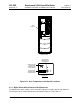
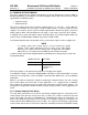
F
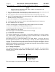
Alarm
RST
SET
Limit Control
Figure 4-7: Digital Alarm Switch Front Panel
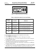
Table 4-6: Digital Alarm Switch Controls and Display
CONTROL or
Display
MEANING
FUNCTION
LED Display TEMP status
Displays current water temperature or
setpoint.
RST RESET Button Resets the unit after an alarm condition.
UP Button Increases the displayed temperature.
DOWN Button Decreases the displayed temperature.
SET SET Button
Used to access and store parameters in the
unit.
Perform the following steps to check or adjust the digital alarm switch settings:
1. Set the ON/OFF to the ON position.
2. Press the SET button on the Digital Alarm Switch. SP will appear in the display.
3. Press the SET button again. The current over-temperature limit value stored in memory will
be displayed. (default = 210°F).
4. If the display does not show the required over-temperature alarm setting, press the ▲ or ▼
arrow button to change the display to the desired temperature setting.
5. Once the desired over-temperature alarm setting (210ºF) is displayed, press the SET button
to store the setting in memory.
6. To calibrate the offset (P1), press and hold the SET button for 8 seconds on the Digital
Alarm Switch. Access code value 0 should appear in the display. The switch comes from the
factory with the code set at 0. AERCO recommends that you do not change this code.