
User Manual

GF-123 Benchmark 2.0LN Low NOx Boiler Chapter 4
OMM-0046_0F Installation, Operation and Maintenance Manual Initial Start-Up
PR1 10/17/12 AERCO International Inc.● 100 Oritani Dr. ● Blauvelt, NY 10913. ● Ph: 800-526-0288 Page 61 of 172
41. Once the oxygen level is within the specified range at 45%, press the ENTER key to store
the selected blower output voltage for the 45% valve position.
42. Press the ▲ arrow key until SET Valve Position appears on the C-MORE display.
43. Press the CHANGE key. SET Valve Position will begin to flash.
44. Press the ▼ arrow key until the SET Valve Position reads 30%, then press the ENTER key.
45. Press the ▼ arrow key until CAL Voltage 30% is displayed.
46. Press the CHANGE key. CAL Voltage 30% will begin to flash.
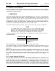
47. The oxygen level at the 30% valve position should be as shown below. Also, ensure that the
carbon monoxide (CO) and nitrogen oxide (NOx) readings do not exceed the values shown.
Table 4-11: Combustion Oxygen Level at
30%
Valve Position
Oxygen %
± 0.2
Carbon Monoxide NOx
8.0 %
<50 ppm
<30 ppm
48. If the oxygen level is not within the specified range, adjust the level using the ▲ and ▼
arrow keys. This will adjust the output voltage to the blower motor as indicated on the
display. Pressing the ▲ arrow key increases the oxygen level and pressing the ▼ arrow key
decreases the oxygen level.
49. Once the oxygen level is within the specified range at 30%, press the ENTER key to store
the selected blower output voltage for the 30% valve position.
50. Press the ▲ arrow key until SET Valve Position appears on the C-MORE display.
51. Press the CHANGE key. SET Valve Position will begin to flash.
52. Press the ▼ arrow key until the SET Valve Position reads 20%, then press the ENTER key.
53. Press the ▼ arrow key until CAL Voltage 16% is displayed.
54. Press the CHANGE key. CAL Voltage 20% will begin to flash.
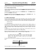
55. The oxygen level at the 20% valve position should be as shown below. Also, ensure that the
carbon monoxide (CO) and nitrogen oxide (NOx) readings do not exceed the values shown.
Table 4-12: Combustion Oxygen Level at
20%
Valve Position
Oxygen %
± 0.2
Carbon Monoxide NOx
8.6 %
<50 ppm
<30 ppm
56. If the oxygen level is not within the specified range, adjust the level using the ▲ and ▼
arrow keys. This will adjust the output voltage to the blower motor as indicated on the
display. Pressing the ▲ arrow key increases the oxygen level and pressing the ▼ arrow key
decreases the oxygen level.
57. Once the oxygen level is within the specified range at 20%, press the ENTER key to store
the selected blower output voltage for 20% valve position.
58. This completes the Propane Combustion Calibration procedure.