Instruction No. GF-123 AERCO INTERNATIONAL, Inc., Northvale, New Jersey, 07647 USA Installation, Operation & Maintenance Instructions Benchmark 2.0 Low NOx Gas Fired Boiler System Natural Gas or Propane Fired Condensing, Modulating, Forced Draft, Hot Water Boiler 2,000,000 BTU/H Input Applicable for Serial Numbers G-10-0927 and above Printed in U.S.A.
Telephone Support Direct to AERCO Technical Support (8 to 5 pm EST, Monday through Friday): 1-800-526-0288 The information contained in this installation, operation and maintenance manual is subject to change without notice from AERCO International, Inc. AERCO International, Inc. 159 Paris Avenue Northvale, NJ 07647-0128 www.aerco,com © AERCO International, Inc.
FOREWORD Foreword The AERCO Benchmark 2.0 Low NOx (LN) Boiler is a modulating unit. It represents a true industry advance that meets the needs of today's energy and environmental concerns. Designed for application in any closed loop hydronic system, the Benchmark's modulating capability relates energy input directly to fluctuating system loads. The Benchmark 2.
CONTENTS GF-123 - AERCO BENCHMARK 2.0LN GAS FIRED LOW NOx BOILER Operating & Maintenance Instructions FOREWORD A Chapter 1 – SAFETY PRECAUTIONS Para. 1-1 1-2 Subject Warnings & Cautions Emergency Shutdown Page 1-1 1-2 1-1 Para. 1-3 Subject Prolonged Shutdown Chapter 2 – INSTALLATION Para. 2.1 2.2 2.3 2.4 2.5 2.6 2.7 2.
CONTENTS Chapter 5 – MODE OF OPERATION Para. 5.1 5.2 5.3 5.4 5.5 Subject Introduction Indoor/Outdoor Reset Mode Constant Setpoint Mode Remote Setpoint Mode Direct Drive Modes Page 5-1 5-1 5-2 5-2 5-3 5-1 Para. 5.6 5.7 Subject Boiler Management System (BMS) Combination Control System (CCS) Page 5-4 5-5 Chapter 6 – SAFETY DEVICE TESTING PROCEDURES 6-1 Para. 6.1 6.2 6.3 6.4 6.5 6.6 6.
CONTENTS Chapter 9 – RS232 COMMUNICATION Para. 9.1 9.2 Subject Introduction RS232 Communication Setup Page 9-1 9-1 9-1 Para. 9.3 9.
SAFETY PRECAUTIONS CHAPTER 1 SAFETY PRECAUTIONS 1.1 WARNINGS & CAUTIONS Installers and operating personnel MUST, at all times, observe all safety regulations. The following warnings and cautions are general and must be given the same attention as specific precautions included in these instructions. In addition to all the requirements included in this AERCO Instruction Manual, the installation of units MUST conform with local building codes, or, in the absence of local codes, ANSI Z223.
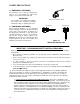
SAFETY PRECAUTIONS 1.2 EMERGENCY SHUTDOWN If overheating occurs or the gas supply fails to shut off, close the manual gas shutoff valve (Figure 1-1) located external to the unit. IMPORTANT MANUAL GAS SHUTOFF VALVE The Installer must identify and indicate the location of the emergency shutdown manual gas valve to operating personnel. 1.
SAFETY PRECAUTIONS Extracted Information From 248 CMR 5.08 (2) – Continued a. In the event that the side wall horizontally vented gas fueled equipment is installed in a crawl space or an attic, the hard wired carbon monoxide detector with alarm and battery back-up may be installed on the next adjacent floor level. b.
INSTALLATION CHAPTER 2 INSTALLATION 2.1 INTRODUCTION This Chapter provides the descriptions and procedures necessary to unpack, inspect and install the AERCO Benchmark 2.0 Low NOx (LN) Boiler. Brief descriptions are also provided for each available mode of operation. Detailed procedures for implementing these modes are provided in Chapter 5.
INSTALLATION 18" 44.5" 24" 79" 101" 30" 24" 24" REAR FRONT 4" HIGH PAD Figure 2-1 Benchmark 2.0LN Boiler Clearances WARNING KEEP THE UNIT AREA CLEAR AND FREE FROM ALL COMBUSTIBLE MATERIALS AND FLAMMABLE VAPORS OR LIQUIDS. CAUTION While packaged in the shipping container, the boiler must be moved by pallet jack or forklift from the FRONT ONLY. USE THE TABS SHOWN IN FIGURE 2-2 TO LIFT AND MOVE THE UNIT. Remove the top panel from the unit to provide access to the lifting tabs.
INSTALLATION If installing a Combination Control Panel (CCP) system, it is important to identify the Combination Mode Boilers in advance and place them in the proper physical location. Refer to Chapter 5 for information on Combination Mode Boilers. 2.5 BOILER RETURN EXHAUST MANIFOLD SUPPLY AND RETURN PIPING The Benchmark 2.0LN Boiler utilizes 4” 150# flanges for the water system supply and return piping connections.
INSTALLATION If a floor drain is not available, a condensate pump can be used to remove the condensate to drain. The maximum condensate flow rate is 20 GPH. The condensate drain trap, associated fittings and drain line must be removable for routine maintenance. COVER THUMB SCREWS (4) FLOAT INLET 3/4 NPT PORT 3/4 NPT PORT OUTLET Figure 2-5 Condensate Trap Cut-Away View 2.7 GAS SUPPLY PIPING The AERCO Benchmark 2.
INSTALLATION TERMINAL BLOCK GAS SUPPLY 2" MANUAL SHUTOFF VALVE DIRT TRAP UPPER RIGHT CORNER OF FRONT PANEL GAS PRESS. REGULATOR (REQUIRED FOR MASSACHUSETTS INSTALLATIONS) Figure 2-6 Manual Gas Shut-Off Valve Location 2.7.4 IRI Gas Train Kit The IRI gas train is an optional gas train configuration which is required in some areas for code compliance or for insurance purposes. The IRI gas train is factory pre-piped and wired. See Appendix F, Drawing AP-A-843 for details. 2.
INSTALLATION 2.9.1 Constant Setpoint Mode 120 VAC, 1 PHASE GND NEU The Constant Setpoint Mode is used when it is desired to have a fixed setpoint that does not deviate. No wiring connections, other than AC electrical power connections, are required for this mode. However, if desired, fault monitoring or enable/disable interlock wiring can be utilized (see paragraphs 2.10.9.1 and 2.10.10). TERMINAL STRIPS L1 Figure 2-8 AC Terminal Block Configurations 2.
INSTALLATION OUTDOOR SENSOR IN SENSOR COMMON (AIR) AUX SENSOR IN REMOTE INTL'K IN EXHAUST SWITCH IN DELAYED INTL'K IN NOT USED NOT USED NC COM NO + ANALOG IN+ B.M.S. (PWM) IN - NC COM NO RS-485 COMM. AUX RELAY 120 VAC, 5A, RES NOT USED SHIELD mA OUT FAULT RELAY 120 VAC, 5A, RES + + G - RELAY CONTACTS: 120 VAC, 30 VDC 5 AMPS RESISTIVE DANGER 120 VAC USED IN THIS BOX NOT USED 0 – 10V AGND Figure 2-10. I/O Box Terminal Strip 2.9.
INSTALLATION 2.9.5 Combination Mode NOTE Only BMS Model 168 can be utilized for the Combination Mode, not the BMS II (Model 5R5-384). With a Combination Mode unit, field wiring is between the unit’s I/O Box wiring terminals, the CCP (Combination Control Panel), and the BMS (Boiler Management System). The wiring must be accomplished using twisted-shielded pair wire from 18 to 22 AWG. Polarity must be maintained.
INSTALLATION 2.10.4 B.M.S. (PWM) IN NOTE Only BMS Model 168 can utilize Pulse Width Modulation (PWM), not the BMS II (Model 5R5-384). These terminals are used to connect the AERCO Boiler Management System (BMS) to the unit. The BMS utilizes a 12 millisecond, ON/OFF duty cycle. This duty cycle is Pulse Width Modulated (PWM) to control the air/fuel valve position. A 0% (open) air/fuel valve position = a 5% ON pulse and a 100% open valve position = a 95% ON pulse. 2.10.
INSTALLATION fault is cleared and the CLEAR button is depressed. The fault relay connections are shown in Figure 2-10. 2.11 AUXILIARY RELAY CONTACTS Each Boiler is equipped with a single pole double throw (SPDT) relay that is energized when there is a demand for heat and deenergized after the demand for heat is satisfied. The relay is provided for the control of auxiliary equipment, such as pumps and louvers, or can be used as a Boiler status indictor (firing or not firing).
INSTALLATION 2.13.3 Sealed Combustion The AERCO Benchmark 2.0LN Boiler is UL listed for 100%-sealed combustion. For sealed combustion installations, the screen on the air inlet duct of the unit must be removed. The inlet air ductwork must then be attached directly to the unit’s air inlet. In a sealed combustion air application, the combustion air ducting pressure losses must be taken into account when calculating the total maximum allowable venting run.
CONTROL PANEL OPERATING PROCEDURES CHAPTER 3 CONTROL PANEL OPERATING PROCEDURES 3.1 INTRODUCTION The information in this Chapter provides a guide to the operation of the Benchmark 2.0LN Boiler using the Control Panel mounted on the front of the unit. It is imperative that the initial startup of this unit be performed by factory trained personnel. Operation prior to initial startup by factory trained personnel will void the equipment warranty.
CONTROL PANEL OPERATING PROCEDURES Table 3-1 Operating Controls, Indicators and Displays ITEM NO. 1 CONTROL, INDICATOR OR DISPLAY LED Status Indicators FUNCTION Four Status LEDs indicate the current operating status as follows: COMM Lights when RS-232 communication is occurring MANUAL Lights when the unit is being controlled using the front panel keypad.
CONTROL PANEL OPERATING PROCEDURES Table 3-1 Operating Controls, Indicators and Displays – Continued ITEM NO. 10 11 CONTROL, INDICATOR OR DISPLAY MENU Keypad FUNCTION Consists of 6 keys which provide the following functions for the Control Panel Menus: MENU Steps through the main menu categories shown in Figure 32. The Menu categories wrap around in the order shown. BACK Allows you to go back to the previous menu level without changing any information.
CONTROL PANEL OPERATING PROCEDURES 3.3 CONTROL PANEL MENUS The Control Panel incorporates an extensive menu structure which permits the operator to set up, and configure the unit. The menu structure consists of five major menu categories which are applicable to this manual. These categories are shown in Figure 3-2. Each of the menus shown, contain options which permit operating parameters to be viewed or changed. The menus are protected by a password levels to prevent unauthorized use.
CONTROL PANEL OPERATING PROCEDURES NOTE 3.5 SETUP MENU The following paragraphs provide brief descriptions of the options contained in each menu. Refer to Appendix A for detailed descriptions of each menu option. Refer to Appendix B for listings and descriptions of displayed startup, status and error messages. 3.4 OPERATING MENU The Operating Menu displays a number of key operating parameters for the unit as listed in Table 3-2.
CONTROL PANEL OPERATING PROCEDURES Table 3-3. Setup Menu Menu Item Display Passsword Available Choices or Limits Minimum Maximum 0 Language 9999 English 12:00 am 11:59 pm Date 01/01/00 12/31/99 Fahrenheit or Celsius Comm Address 0 Baud Rate 127 2400, 4800, 9600, 19.2K Software Ver 0.00 Fahrenheit 0 9600 Ver 9.99 3.
CONTROL PANEL OPERATING PROCEDURES Table 3-4. Configuration Menu - Continued Menu Item Display Remote Signal (If Mode = Remote Setpoint, Direct Drive or Combination) Available Choices or Limits Minimum Maximum 4 – 20 mA/1 – 5V 0 -20 mA/0 – 5V PWM Input (BMS) Network Default 4 – 20 mA, 1-5V Bldg Ref Temp (If Mode = Outdoor Reset) 40°F 230°F 70°F Reset Ratio (If Mode = Outdoor Reset) 0.1 9.9 1.
CONTROL PANEL OPERATING PROCEDURES 3.7 TUNING MENU The Tuning Menu items in Table 3-5 are Factory set for each individual unit. Do not change these menu entries unless specifically requested to do so by Factory-Trained personnel. 3.8 COMBUSTION CAL MENU The Combustion Cal Table 3-6 are used unit’s blower motor and air density at (Calibration) Menu items in to vary the speed of the based on air temperature prescribed Air/Fuel Valve positions (% open).
CONTROL PANEL OPERATING PROCEDURES 1. The DEMAND LED status indicator will light. 2. The unit checks to ensure that the Proof of Closure (POC) switch in the downstream Safety Shut-Off Valve (SSOV) is closed. See Figure 3-3 for SSOV location. GAS INLET (b) The igniter relay is activated and provides ignition spark. (c) The gas Safety Shut-Off Valve (SSOV) is energized (opened) allowing gas to flow into the Air/Fuel Valve. SSOV TO AIR/FUEL VALVE MANUAL SHUT-OFF VALVE Figure 3-3. SSOV Location 3.
CONTROL PANEL OPERATING PROCEDURES 8. With the unit firing properly, it will be controlled by the temperature controller circuitry. The boiler’s VALVE POSITION will be continuously displayed on the front panel bargraph. Once the demand for heat has been satisfied, the Control Box will turn off the dual SSOV gas valves. The blower relay will be deactivated and the Air/Fuel Valve will be closed. Standby will be displayed. 3.
INITIAL START-UP CHAPTER 4 4.1 INITIAL START-UP REQUIREMENTS The requirements for the initial start-up of the Benchmark 2.0 Low NOx (LN) Boiler consist of the following: • • • • • Complete installation Perform combustion calibration Set proper controls and limits Set up mode of operation (see Chapter 5) Test safety devices (see Chapter 6) Installation should be fully completed before performing initial start-up. The start-up must be complete prior to putting the unit into service.
INITIAL START-UP 5. Attach one end of the plastic tubing to the barbed fitting and the other end to the 16 inch W.C. manometer. SSOV GAS INLET HIGH GAS PRESSURE SWITCH 1/8" NPT PLUG (INSTALL MANOMETER HERE) LOW GAS PRESSURE SWITCH TO AIR/ FUEL VALVE MANUAL SHUT-OFF VALVE Figure 4-1. 1/8" NPT Plug Location On Leak Detection Ball Valve 4.2.3 Accessing the Analyzer Probe Port The unit contains NPT plugs on the left and right side of the exhaust manifold at the rear of the unit as shown in Figure 4-2.
INITIAL START-UP gas pressure adjustment screw (Figure 4-3). Make gas regulator adjustments using a flattip screwdriver to obtain 2.8” W.C. BRASS HEX HEAD CAP (REMOVE TO ACCESS GAS PRESSURE ADJUSTMENT SCREW) 14. If necessary, adjust the iris air damper shown in Figure 4-4 until the oxygen level is within the range specified in Table 4-1. 15. Once the oxygen level is within the specified range at 100%, lower the valve position to 80%.
INITIAL START-UP 16. Press the MENU Key on the front panel of the C-MORE and access the Setup menu. Enter password 6817 and then press the ENTER key. 17. Press the MENU Key on the front panel of the C-MORE until Combustion Cal Menu appears on the C-More display. 18. Press the ▲ arrow key until SET Valve Position appears on the C-MORE display. 19. Press the CHANGE key. SET Valve will begin to flash. 20. Press the ▲ arrow key until the SET Valve Position reads 80%. Press the ENTER key. 21.
INITIAL START-UP Combustion Oxygen Level at 45% Valve Position Oxygen % ± 0.2 7.2 % Carbon Monoxide <50 ppm NOx <30 ppm 40. If the oxygen level is not within the specified range, adjust the level using the ▲ and ▼ arrow keys. This will adjust the output voltage to the blower motor as indicated on the display. Pressing the ▲ arrow key increases the oxygen level and pressing the ▼ arrow key decreases the oxygen level. 41.
INITIAL START-UP IMPORTANT The unit is shipped from the factory set up for either Natural Gas or Propane as specified by the Style No. on the Sales Order. Since the required gas pressures and oxygen (O2) levels for Propane differ from those required for Natural Gas, the Propane Combustion Calibration procedures are repeated in paragraph 4.4. 4.4 PROPANE COMBUSTION CALIBRATION The Benchmark 2.0LN Boiler is combustion calibrated at the factory prior to shipping.
INITIAL START-UP 16. Press the MENU Key on the front panel of the C-MORE and access the Setup menu. Enter password 6817 and then press the ENTER key. 17. Press the MENU Key on the front panel of the C-MORE until Combustion Cal Menu appears on the C-More display. 18. Press the ▲ arrow key until SET Valve Position appears on the C-MORE display. 19. Press the CHANGE key. SET Valve Position will begin to flash. 20. Press the ▲ arrow key until the SET Valve Position reads 80%. Press the ENTER key. 21.
INITIAL START-UP Combustion Oxygen Level at 45% Valve Position Oxygen % ± 0.2 6.0 % Carbon Monoxide <50 ppm NOx <30 ppm 40. If the oxygen level is not within the specified range, adjust the level using the ▲ and ▼ arrow keys. This will adjust the output voltage to the blower motor as indicated on the display. Pressing the ▲ arrow key increases the oxygen level and pressing the ▼ arrow key decreases the oxygen level. 41.
INITIAL START-UP 4.6 OVER-TEMPERATURE LIMIT SWITCHES The unit contains both automatic and manual reset over-temperature limit switches. These switches are mounted on a plate as shown in Figure 4-5. The switches can be accessed by opening the front panel door of the unit. The manual reset switch is not adjustable and is permanently fixed at 210°F. This switch will shut down and lock out the boiler if the water temperature exceeds 210°F.
MODE OF OPERATION CHAPTER 5 MODE OF OPERATION 5.1 INTRODUCTION The boiler is capable of being operated in any one of six different modes. The following paragraphs in this Chapter provide descriptions of each of these operating modes. Each boiler is shipped from the factory tested and configured for the ordered mode of operation. All temperature related parameters are at their factory default values which work well in most applications.
MODE OF OPERATION 7. Press the CHANGE key. The display will begin to flash. 8. Use the ▲ and ▼ arrow keys to select the desired Building Reference Temperature. 9. Press ENTER to save any changes. 10. Next, scroll through the Configuration Menu until the display shows Reset Ratio. 11. Press the CHANGE key. The display will begin to flash. 12. Use the ▲ and ▼ arrow keys to select the Reset Ratio determined in step 5. 13. Press ENTER to save the change. Refer to paragraph 3.
MODE OF OPERATION If the Network setting is selected for RS485 Modbus operation, a valid Comm Address must be entered in the Setup Menu. Refer to Modbus Communication Manual GF-114 for additional information. While it is possible to change the settings of temperature related functions, the unit is factory preset with settings that work well in most applications. It is suggested that an AERCO representative be contacted, prior to changing any temperature related function settings.
MODE OF OPERATION If the Network setting is selected for RS485 Modbus operation, a valid Comm Address must be entered in the Setup Menu. Refer to Modbus Communication Manual GF-114 for additional information. 5.5.1 Direct Drive Field Wiring The only wiring connections necessary for Direct Drive mode are connection of the remote signal leads from the source to the unit’s I/O Box. For either a 4-20mA/0-5V or a 0-20mA/0-5V setting, the connections are made at the ANALOG IN terminals in the I/O Box.
MODE OF OPERATION To change back to the BMS mode, simply press the AUTO/MAN switch. The REMOTE LED will again light and the MANUAL LED will go off. 5.7 COMBINATION CONTROL SYSTEM (CCS) NOTE Only BMS Model 168 can be utilized for the Combination Mode, not the BMS II (Model 5R5-384). A Combination Control System (CCS) is one that uses multiple boilers to cover both spaceheating and domestic hot water needs.
SAFETY DEVICE TESTING CHAPTER 6 SAFETY DEVICE TESTING 6.1 TESTING OF SAFETY DEVICES Periodic safety device testing is required to ensure that the control system and safety devices are operating properly. The boiler control system comprehensively monitors all combustion-related safety devices before, during and after the start sequence. The following tests check to ensure that the system is operating as designed. 4.
SAFETY DEVICE TESTING 6.3 HIGH GAS PRESSURE TEST To simulate a high gas pressure fault, refer to Figure 6-1 and proceed as follows: shut the unit off immediately and refer fault to qualified service personnel. 7. Close the drain and pressure relief valve used in draining the unit. 1. Remove the 1/8“ plug from the leak detection ball valve shown in Figure 6-1. 8. Open the water shut-off valve in the return piping to the unit. 2. Install a 0 – 16” W.C. manometer (or W.C.
SAFETY DEVICE TESTING 6.6 INTERLOCK TESTS The unit is equipped with two interlock circuits called the Remote Interlock and Delayed Interlock. Terminal connections for these circuits are located in the I/O Box (Figure 2-9) and are labeled REMOTE INTL’K IN and DELAYED INTL’K IN. These circuits can shut down the unit in the event that an interlock is opened. These interlocks are shipped from the factory jumpered (closed).
SAFETY DEVICE TESTING 6. Press the CLEAR button to reset the fault 7. The unit should start. 6.7 FLAME FAULT TESTS Flame faults can occur during ignition or while the unit is already running. To simulate each of these fault conditions, proceed as follows: 1. Set the ON/OFF switch to the OFF position. 2. Place the unit in the Manual Mode and set the valve position between 25% and 30%. 3.
SAFETY DEVICE TESTING 5. Re-enable the blower output drive voltage by performing the following steps: 6. The unit should fault and display SSOV SWITCH OPEN. (a) Press the MENU key until CONFIGURATION MENU is displayed. 7. Replace wire #148 and press the CLEAR button. (b) Press the ▲ arrow key until the ANALOG OUTPUT function is displayed, then press the CHANGE key. 8. Set the ON/OFF switch to ON to start the unit.
SAFETY DEVICE TESTING 5. The unit should begin it’s start sequence, then shut down and display PRG SWITCH OPEN DURING PURGE. 6. Replace the wire on the Purge Switch and depress the CLEAR button. The unit should restart. 6.11 IGNITION SWITCH OPEN DURING IGNITION 3. Remove the Air/Fuel Valve cover (Figure 6-5) by rotating the cover counterclockwise to unlock and lift up to remove. 4. Remove one of the two wires (#169 or #170) from the Ignition Switch (Figure 6-6). 170 2 17 2.
MAINTENANCE CHAPTER 7 MAINTENANCE 7.1 MAINTENANCE SCHEDULE The unit requires regular routine maintenance to keep up efficiency and reliability. For best operation and life of the unit, the following routine maintenance procedures should be performed in the time periods specified in Table 7-1. See Appendix I for a complete CSD-1 inspection check list.
MAINTENANCE 7.2 IGNITOR-INJECTOR The ignitor-injector (part no. 58023) is located on the burner plate at the top of the boiler. In addition to providing the ignition spark required to light the burner, the ignitor-injector also contains a gas injector tube which connects to the staged ignition assembly. Figure 7-1 shows the complete burner assembly removed from the boiler and indicates the location of the ignitorinjector flame detector and other related components.
MAINTENANCE NOTE If a replacement ignitor-injector (part no. 58023) is being installed, a compression nut containing a built-in ferrule will be included with the replacement part. If needed, 3 indexing washers are also included These washers may be needed to properly position the gas injector tube of the ignitor-injector within the 120° angle shown in Figure 7-3. BLOWER GAS INJECTOR TUBE IGNITORINJECTOR 3. Disconnect the lead wire from the flame detector. 4.
MAINTENANCE To inspect or replace the burner assembly: 1. Set the ON/OFF switch on the control panel, to the OFF position. Disconnect AC power from the unit and turn off the gas supply. 2. Remove the side and top panels from the unit to provide access to the burner assembly. See Figure 7-4. 3. Disconnect the lead wire from the flame detector installed on the burner plate (Figure 7-4). 4. Remove the two (2) screws securing the flame detector to the plate.
MAINTENANCE BLOWER PROOF SWITCH BLOCKED INLET SWITCH BLOWER AIR/FUEL VAVLE 19. Beginning with the burner assembly removed in step 17, reinstall all the components in the reverse order that they were removed. During reassembly, replace the gaskets for the blower and flame detector with new parts. 20. Make sure to align the ignitor-injector and flame detector tapped holes in the burner plate with the heat exchanger top head.
MAINTENANCE 4. Remove the float from the condensate trap. 5. Remove the orifice gasket from the trap. 6. Thoroughly clean the trap and gasket. Also inspect the drain piping for blockage. If the trap cannot be thoroughly cleaned, replace the trap. 7. After the above items have been inspected and thoroughly cleaned, replace the orifice gasket and float in the condensate trap and replace the trap cover. 8. Reassemble all piping and hose connections to the condensate trap inlet and outlet.
TROUBLESHOOTING Chapter 8- TROUBLESHOOTING GUIDE 8.1 INTRODUCTION This troubleshooting guide is intended to aid service/maintenance personnel in isolating the cause of a fault in a Benchmark 2.0 Boiler. The troubleshooting procedures contained herein are presented in tabular form on the following pages. These tables are comprised of three columns labeled: Fault Indication, Probable Cause and Corrective Action. The numbered items in the Probable Cause and Corrective Action columns correspond to each other.
TROUBLESHOOTING TABLE 8-1. BOILER TROUBLESHOOTING FAULT INDICATION PROBABLE CAUSES TROUBLESHOOTING/CORRECTIVE ACTION AIRFLOW FAULT DURING IGNITION 1. Blower stopped running due to thermal or current overload 2. Blocked Blower inlet or inlet ductwork 1. Check combustion blower for signs of excessive heat or high current drain that may trip thermal or current overload devices. 2. Inspect the inlet to the combustion blower including any ductwork leading up to the combustion blower for signs of blockage.
TROUBLESHOOTING TABLE 8-1. BOILER TROUBLESHOOTING – Continued FAULT INDICATION PROBABLE CAUSES TROUBLESHOOTING/CORRECTIVE ACTION AIRFLOW FAULT DURING PURGE 1. Blower not running or running too slow 1. Start the unit. If the blower does not run check the blower solid state relay for input and output voltage. If the relay is okay, check the blower. 2. Start the unit. If the blower runs, check the airflow switch for continuity. Replace the switch if there is no continuity. 3.
TROUBLESHOOTING TABLE 8-1. BOILER TROUBLESHOOTING – Continued FAULT INDICATION DELAYED INTERLOCK OPEN DIRECT DRIVE SIGNAL FAULT FLAME LOSS DURING IGN PROBABLE CAUSES 1. Delayed Interlock Jumper not installed or removed. 2. Device proving switch hooked to interlocks is not closed 1. Direct drive signal is not present: Not yet installed. Wrong polarity. Signal defective at source. Broken or loose wiring. 2. Signal is not isolated (floating). 3.
TROUBLESHOOTING TABLE 8-1. BOILER TROUBLESHOOTING – Continued FAULT INDICATION (continued) FLAME LOSS DURING RUN HEAT DEMAND FAILURE HIGH GAS PRESSURE PROBABLE CAUSES 8. Defective staged ignition solenoid valve. 9. Clogged staged ignition piece. 8. When boiler goes to ignition, listen to solenoid valve to ensure it is opening. 9. Remove and inspect staged ignition piece for blockage. 10. Carbon or other debris on burner Remove the burner and inspect for any carbon or debris. Clean and reinstall 1.
TROUBLESHOOTING TABLE 8-1. BOILER TROUBLESHOOTING – Continued FAULT INDICATION PROBABLE CAUSES TROUBLESHOOTING/CORRECTIVE ACTION (continued) 3. Defective High Gas Pressure Switch 3. Remove the leads from the high gas pressure switch and measure continuity across the common and normally closed terminals with the unit not firing. Replace the switch if it does not show continuity. 4. See Figure 8-1. Ensure that the gas pressure snubber is installed at the high gas pressure switch. 5.
TROUBLESHOOTING TABLE 8-1. BOILER TROUBLESHOOTING – Continued FAULT INDICATION IGN SWTCH CLOSED DURING PURGE PROBABLE CAUSES 1. Air/Fuel Valve not rotating 2. Defective or shorted switch 3. Switch wired incorrectly 4. Defective Power Supply Board or fuse 5. Defective IGST Board IGN SWTCH OPEN DURING IGNITION 1. Air/Fuel Valve not rotating to ignition position. 2. Defective ignition switch 3. Defective Power Supply Board or fuse 4. Defective IGST Board INTERLOCK OPEN 1.
TROUBLESHOOTING TABLE 8-1. BOILER TROUBLESHOOTING – Continued FAULT INDICATION LINE VOLTAGE OUT OF PHASE LOW GAS PRESSURE PROBABLE CAUSES 1. Line and Neutral switched in AC Power Box. 2. Incorrect power supply transformer wiring. 1. Incorrect supply gas pressure. 2. Defective Low Pressure Gas Switch LOW WATER LEVEL 1. Insufficient water level in system 2. Defective water level circuitry. 3. Defective water level probe. MODBUS COMM FAULT PRG SWTCH CLOSED DURING IGNITION 1.
TROUBLESHOOTING TABLE 8-1. BOILER TROUBLESHOOTING – Continued FAULT INDICATION PRG SWTCH OPEN DURING PURGE PROBABLE CAUSES 1. Defective purge switch. 2. No voltage present at switch. 3. Switch wired incorrectly. 4. Defective Power Supply Board or fuse 5. Defective IGST Board OUTDOOR TEMP SENSOR FAULT 1. Loose or broken wiring. 2. Defective Sensor. 3. Incorrect Sensor. REMOTE SETPT SIGNAL FAULT RESIDUAL FLAME 1. Remote setpoint signal not present: Not yet installed. Wrong polarity.
TROUBLESHOOTING TABLE 8-1. BOILER TROUBLESHOOTING – Continued FAULT INDICATION SSOV FAULT DURING PURGE SSOV FAULT DURING RUN SSOV RELAY FAILURE PROBABLE CAUSES See SSOV SWITCH OPEN 1. SSOV switch closed for 15 seconds during run. 1. Replace or adjust microswitch in SSOV actuator. If fault persists, replace actuator. 1. SSOV relay failed on board. 1. Press CLEAR button and restart unit. If fault persists, replace Ignition/Stepper (IGST) Board. 2.
TROUBLESHOOTING 8.2 ADDITIONAL FAULTS WITHOUT SPECIFIC FAULT MESSAGES Refer to Table 8-2 to troubleshoot faults which may occur without a specific fault message being displayed. TABLE 8-2. BOILER TROUBLESHOOTING WITH NO FAULT MESSAGE DISPLAYED OBSERVED INCIDENT Hard Light-Off Fluctuating Gas Pressure Air/Fuel Valve “hunting” at 80% Valve Position 8-11 PROBABLE CAUSES 1. Staged Ignition Ball Valve closed. 2. Clogged/damaged Gas Injector (Figure 8-2). 3.
TROUBLESHOOTING HIGH GAS PRESSURE SWITCH DAMPING ORIFICE TO AIR/FUEL VALVE SSOV SNUBBER LOW GAS PRESSURE SWITCH MANUAL SHUT-OFF VALVE GAS INLET STAGED IGNITION LINE BALL VALVE Figure 8-1 High Pressure Gas Switch & Snubber Locations Figure 8-2 Staged Ignition Solenoid Location 8-12 SSOV ACTUATOR WITH GAS PRESSURE ADJUSTMENT Figure 8-3 Damping Orifice Location
RS232 COMMUNICATION CHAPTER 9 RS232 COMMUNICATION 9.1 INTRODUCTION The RS232 port on the front panel of the C-More Control Box (Figure 3-1) can be interfaced to a laptop computer or other suitable terminal using a RS232 adapter cable. RS232 communication can be accomplished using any “Dumb Terminal” emulation, such as “Hyper Terminal” which is included with Microsoft Windows.
RS232 COMMUNICATION (c) Menu changes will be stored in nonvolatile memory. 9. To redisplay the menu and view the option which was just changed in step 5, enter D and press . 10. To display the Fault (F) Log, Sensor (S) Log or Time (T) Line Log, press F, S or T followed by . Refer to paragraph 9.4 for descriptions and samples of these data logs. 11. To log off and terminate the RS232 communication link, press L followed by . 9.
RS232 COMMUNICATION Table 9-1. Sample Fault Log Display No. 0 1 2 Fault Message Direct Drive Signal Fault Low Gas Pressure Loss of Power Cycle 609 366 0 Date 1/10/02 7/04/01 1/01/01 Time 8:42am 5:29pm 11:50am Table 9-2.
APPENDIX A APPENDIX A - BOILER MENU ITEM DESCRIPTIONS MENU LEVEL & OPTION DESCRIPTION OPERATING MENU Active Setpoint This is the setpoint temperature to which the control is set when operating in the Constant Setpoint, Remote Setpoint or Outdoor Reset Mode. When in the Constant Setpoint Mode, this value is equal to the Internal Setpoint setting in the Configuration Menu. When in the Remote Setpoint Mode, this value is the setpoint equivalent to the remote analog signal supplied to the unit.
APPENDIX A APPENDIX A - BOILER MENU ITEM DESCRIPTIONS - CONTINUED MENU LEVEL & OPTION DESCRIPTION SETUP MENU Password Allows password to be entered. Once the valid password (159) is entered, options in the Setup, Configuration and Tuning Menus can be modified. Language Permits selection of English, Spanish or French for displayed messages. Default is English. Time Displays time from 12:00 am to 11:59 pm.
APPENDIX A APPENDIX A - BOILER MENU ITEM DESCRIPTIONS - Continued MENU LEVEL & OPTION DESCRIPTION CONFIGURATION MENU (Cont.) Reset Ratio Permits setting of Reset Ratio when operating boiler in the Outdoor Reset Mode. Reset Ratio is adjustable from 0.1 to 9.9. Default is 1.2. Outdoor Sensor Allows outdoor sensor function to be enabled or disabled. Default is disabled. System Start Tmp If outdoor sensor is enabled, this menu item allows the system start temperature to be set from 30 to 100°F.
APPENDIX A APPENDIX A - BOILER MENU ITEM DESCRIPTIONS - Continued MENU LEVEL & OPTION DESCRIPTION CONFIGURATION MENU (Cont.) HI DB Setpt EN Operating at a Valve Position below this value will inhibit the DEADBAND feature. When operating at a Valve Position below this value, the effective Setpoint is equal to Active Setpoint + DEADBAND HIGH. Setting range is from 0 to 100. (Default is 30) Demand Offset This entry will reduce excessive ON/OFF cycling in AUTO mode.
APPENDIX A MENU LEVEL & OPTION DESCRIPTION TUNING MENU Prop Band Generates a fire rate based on the error that exists between the setpoint temperature and the actual outlet temperature. If the actual error is less than the proportional band setting (1 to 120°F), the fire rate will be less than 100%. If the error is equal to or greater than the proportional band setting, the fire rate will be 100%.
APPENDIX B APPENDIX B - STARTUP, STATUS AND FAULT MESSAGES TABLE B-1. STARTUP AND STATUS MESSAGES MESSAGE DEMAND DELAY XX sec DISABLED HH:MM pm, pm MM/DD/YY FLAME PROVEN IGNITION TRIAL XX sec PURGING XX sec STANDBY WAIT WARMUP XX sec DESCRIPTION Displayed if Demand Delay is active. Displayed if ON/OFF switch is set to OFF. The display also shows the time (am or pm) and date that the unit was disabled. Displayed after flame has been detected for a period of 2 seconds.
APPENDIX B TABLE B-2.
APPENDIX B TABLE B-2. FAULT MESSAGES - Continued FAULT MESSAGE OUTDOOR TEMP SENSOR FAULT OUTLET TEMP SENSOR FAULT PRG SWTCH CLOSED DURING IGNITION PRG SWTCH OPEN DURING PURGE REMOTE SETPT SIGNAL FAULT RESIDUAL FLAME SSOV SWITCH OPEN SSOV FAULT DURING PURGE SSOV FAULT DURING IGN SSOV FAULT DURING RUN SSOV RELAY FAILURE STEPPER MOTOR FAILURE FAULT DESCRIPTION The temperature measured by the Outdoor Air Sensor is out of range.
APPENDIX C TEMPERATURE SENSOR RESISTANCE VOLTAGE CHART (BALCO) TEMP (°F) -40 -30 -20 -10 0 10 20 30 40 50 60 70 80 90 100 110 120 130 140 150 160 170 180 190 200 210 220 230 240 250 RES (OHMS) 779.0 797.5 816.3 835.4 854.8 874.6 894.7 915.1 935.9 956.9 978.3 1000.0 1022.0 1044.4 1067.0 1090.0 1113.3 1137.0 1160.9 1185.2 1209.5 1234.7 1260.0 1285.6 1311.4 1337.7 1364.2 1391.0 1418.2 1445.7 VOLTS* 1.93 1.96 1.99 2.02 2.05 2.07 2.10 2.12 2.15 2.17 2.20 2.23 2.25 2.27 2.30 2.32 2.34 2.36 2.39 2.41 2.43 2.
APPENDIX D APPENDIX D. - INDOOR/OUTDOOR RESET RATIO CHARTS Table D-1. Header Temperature for a Building Reference Temperature of 50F RESET RATIO Air Temp 0.6 0.8 1.0 1.2 1.4 1.6 1.8 2.0 2.2 2.
APPENDIX D Table D-3. Header Temperature for a Building Reference Temperature of 65F RESET RATIO Air Temp 0.6 0.8 1.0 1.2 1.4 1.6 1.8 2.0 2.2 2.
APPENDIX D Table D-5. Header Temperature for a Building Reference Temperature of 75F RESET RATIO Air Temp 0.6 0.8 1.0 1.2 1.4 1.6 1.8 2.0 2.2 2.
APPENDIX D Table D-7. Header Temperature for a Building Reference Temperature of 90F RESET RATIO Air Temp 0.6 0.8 1.0 1.2 1.4 1.6 1.8 2.0 2.2 2.
APPENDIX E BOILER DEFAULT SETTINGS MENU & OPTION FACTORY DEFAULT Setup Menu Password 0 Language English Unit of Temp Comm Address Baud Rate Fahrenheit 0 9600 Configuration Menu Internal Setpt 130°F Unit Type BMK Boiler LN Unit Size 2.0 MBTU Boiler Mode Constant Setpoint Remote Signal (If Mode = Remote Setpoint, Direct Drive or Combination) 4 – 20 mA / 1-5V Bldg Ref Temp (If Boiler Mode = Outdoor Reset) 70°F Reset Ratio (If Boiler Mode = Outdoor Reset) 1.
APPENDIX E BOILER DEFAULT SETTINGS - Continued MENU & OPTION FACTORY DEFAULT Configuration Menu --Continued Network Timeout 30 seconds Hi DB Setpt En 30 Demand Offset 10 Deadband High 2 Deadband Low 2 Tuning Menu Prop Band 70°F Integral Gain 1.00 Derivative Time E-2 0.
210 240 7.00 (17.8) 7-3/4 (19.7) 8" EXHAUST OUTLET 12-3/4 (32.4) 13-1/4 (33.7) 56 (142.2) 1-1/2" NPT DRAIN CONN. 23-1/2 (59.7) 7-1/2 (19.1) 1-1/4 (3.2) 2-1/2 (6.4) CONDENSATE DRAIN PRESS./TEMP. GAUGE 17-1/2 (44.5) 18-3/4 (47.6) NAT. GAS WITH FM GAS TRAIN NAT. GAS WITH IRI GAS TRAIN DIM. "A" 79 (200.7) 28 (71.1) DWN.BY JK SCALE CHKD. REV.DATE DATE092608 SIZE APPD. AP-A-798 BENCHMARK 2 MIL. BTU LOW NOx GAS FIRED BOILER DIMENSIONAL DRAWING INTERNATIONAL, INC.
F-2 2) ALL DIMENSIONS SHOWN ARE IN INCHES (CENTIMETERS) NOTES: 1) ALL HOLES ARE FLUSH WITH THE BOTTOM SURFACE OF THE FRAME FRONT INTERNATIONAL, INC. NORTHVALE, NJ 07647 *NOT TO SCALE* DRWN BY:SJD DATE:10/12/07 SD - A - 730 B REV BENCHMARK 1.5 / 2.
ENTIRE BMK2.0 LN FM GAS TRAIN P/N: 22064-1 2" - SCH. 40 PIPE LOW GAS PRESSURE SWITCH P/N: 61002-1 HIGH GAS PRESSURE SWITCH P/N: 61002-12 FULL PORT BALL VALVE 1.50" NPT P/N: 92006-7 TO A/F VALVE ASSY. TEST COCK INTERNATIONAL, INC. NORTHVALE, NJ 07647 *NOT TO SCALE* DRWN BY:SJD DATE:2/12/09 AP - A - 842 B REV BENCHMARK 2.0 LOW NOx FM GAS TRAIN AERCO 1/8" NPT PLUG (INSTALL MANOMETER HERE) GAS PRESSURE SNUBBER P/N: 99017 1.
F-4 1.5" FULL PORT BALL VALVE P/N: 92006-7 2" SCH.40 PIPE 3/4" SCH.40 PIPE LOW GAS PRESSURES SWITCH P/N: 61002-1 VENT TO ATMOSPHERE PER ANSI Z223.1 (NFPA54) NORMALLY OPEN VENT VALVE P/N: GP-122774 INTERNATIONAL, INC. NORTHVALE, NJ 07647 *NOT TO SCALE* DRWN BY:SJD DATE:10/12/09 AP - A - 843 C REV BENCHMARK 2.0 LOW NOx IRI GAS TRAIN AERCO 1.5" DOUBLE-BODY SSOV CONNECTING FLANGE (QTY. 2) P/N 124178 1.
APPENDIX F F-5
APPENDIX F F-6
APPENDIX F OTHER DUAL FUEL COMPONENTS CONTROLS ITEM PART NO. QTY DESCRIPTION 30 123966 1 OVER TEMP SWITCH AUTO 31 123552 1 OVER TEMP SWITCH MANUAL 32 61002-5 1 BLOCKED INLET SWITCH 33 60011-2 1 BLOWER PROOF SWITCH 34 161560 1 35 181197 1 36 GP-122464 1 IGNITION TRANSFORMER 37 33048 1 VFD MOUNTING BRACKET (1) 39 61024 1 (1) 41 GP- 122569 1 IGNITION CABLE ASSY. (1) 42 63016-1 1 BMK2.
APPENDIX F F-8
APPENDIX F F-9
APPENDIX F F-10
APPENDIX F F-11
APPENDIX F F-12
1-1/2" NPT DRAIN CONN. SYSTEM PUMP * CONDENSATE DRAIN TRAP AIR SEPARATOR AUTOMATIC AIR VENT P&T RELIEF VALVE (TYP.) 7) A GAS REGULATOR IS MANDATORY FOR THE STATE OF MASSACHUSETTS, REGARDLESS OF SUPPLY PRESSURE. SEE DIAGRAM 1 BE 6'' AWAY FROM SIDE PANELS. 5) THIS IS A TYPICAL INSTALLATION DRAWING. LOCAL CODES AND AUTHORITIES SHOULD BE CONSULTED. 6) WHEN AVAILABLE GAS PRESSURE IS GREATER THAN 2.
G-2 1-1/2" NPT DRAIN CONN. SYSTEM PUMP * CONDENSATE DRAIN TRAP AIR SEPARATOR AUTOMATIC AIR VENT P&T RELIEF VALVE (TYP.) FREELY, BY GRAVITY, TO A CONVENIENT FLOOR DRAIN. RELIEF VALVE SHOULD BE PIPED VERTICALLY TO A SEE DIAGRAM 1 7) A GAS REGULATOR IS MANDATORY FOR THE STATE OF MASSACHUSETTS, REGARDLESS OF SUPPLY PRESSURE. 6) WHEN AVAILABLE GAS PRESSURE IS GREATER THAN 2.0 PSIG, A LOCK-UP STYLE REGULATOR MUST BE INSTALLED DOWNSTREAM OF THE 2" MANUAL SHUTOFF VALVE TO BRING THE GAS PRESSURE DOWN TO 2.
* 2" MANUAL SHUTOFF VALVE DRIP TRAP GAS SUPPLY AUTOMATIC AIR VENT P&T AIR SEPARATOR * CONDENSATE DRAIN TRAP 1-1/2" NPT DRAIN CONN. SYSTEM PUMP P&T P&T RELIEF VALVE (TYP.) 7) A GAS REGULATOR IS MANDATORY FOR THE STATE OF MASSACHUSETTS, REGARDLESS OF SUPPLY PRESSURE. SEE DIAGRAM 1 6) WHEN AVAILABLE GAS PRESSURE IS GREATER THAN 2.0 PSIG, A LOCK-UP STYLE REGULATOR MUST BE INSTALLED DOWNSTREAM OF THE 2" MANUAL SHUTOFF VALVE TO BRING THE GAS PRESSURE DOWN TO 2.0 PSIG.
APPENDIX G G-4
APPENDIX H H-1
APPENDIX H H-2
APPENDIX H H-3
APPENDIX H CONTROL BOX CONNECTORS 16-PIN CONNECTOR 24-PIN CONNECTOR 1 231 2 3 232 4 5 234 233 6 7 236 235 9 10 11 12 8 237 238 240 239 241 13 14 15 16 17 18 19 20 21 22 23 24 242 244 243 245 246 250 247 251 252 253 16 254 226 J3 1 2 3 4 5 6 7 8 9 10 11 12 13 14 15 1 2 3 4 5 6 7 220 221 8 219 7 6 216 5 4 215 3 2 213 214 1 212 211 J2 8 1 2 3 4 5 6 7 8 9 10 11 12 1 OUT 2 IN REMOTE INTLK 3 IN EXHAUST TEMP OUT 5 4 DEL
APPENDIX I RECOMMENDED PERIODIC TESTING CHECK LIST WARNING NOTE: Periodic testing of all boiler controls and safety devices is required to determine that they are operating as designed. Precautions shall be taken while tests are being performed to protect against bodily injury and property damage. The owner or user of an automatic boiler system should set up a formal system of periodic preventive maintenance and testing. Tests should be conducted on a regular basis and the results recorded in a log-book.
APPENDIX J BENCHMARK CONTROL PANEL EXPLODED VIEW J-1
P1 P2 P3 P4 P5 P6 APPENDIX J BENCHMARK CONTROL PANEL REAR VIEW J-2
APPENDIX K RECOMMENDED SPARE PARTS LISTS NOTE Refer to the Parts List Illustrations in Appendix F for the locations of the recommended and optional spare parts listed in the following Tables. Table K-1.
Standard Warranty: Benchmark Gas-Fired Hydronic Boiler International, Inc. PRESSURE VESSEL/HEAT EXCHANGER: 10 YEARS FROM SHIPMENT The pressure vessel/heat exchanger shall carry a 10-year prorated, limited warranty from shipment against any failure due to condensate corrosion, thermal stress, mechanical defects or workmanship. Operation of the boiler using contaminated air will void the warranty.
Standard Warranty: Benchmark Gas-Fired Hydronic Boiler International, Inc. CONDITIONS OF WARRANTY Should an AERCO gas-fired Hydronic boiler fail for any of the above reasons within the specified time period from the date of original shipment(s), AERCO shall, at its option, modify, repair or exchange the defective item. AERCO shall have the option of having the item returned, FOB its factory, or to make field replacements at the point of installation.