Instruction No. GF-123M AERCO INTERNATIONAL, Inc., Northvale, New Jersey, 07647 USA Installation, Operation & Maintenance Instructions Benchmark 2.0 Low NOx Natural Gas Fired Boiler System Condensing, Modulating Forced Draft, Hot Water Boiler 2,000,000 BTU/H Input Printed in U.S.A.
Telephone Support Direct to AERCO Technical Support (8 to 5 pm EST, Monday through Friday): 1-800-526-0288 The information contained in this installation, operation and maintenance manual is subject to change without notice from AERCO International, Inc. AERCO International, Inc. 159 Paris Avenue Northvale, NJ 07647-0128 www.aerco,com © AERCO International, Inc.
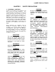
FOREWORD Foreword The AERCO Benchmark 2.0LN Boiler is a modulating unit. It represents a true industry advance that meets the needs of today's energy and environmental concerns. Designed for application in any closed loop hydronic system, the Benchmark's modulating capability relates energy input directly to fluctuating system loads. The Benchmark 2.
CONTENTS GF-123 - AERCO BENCHMARK 2.0LN GAS FIRED LOW NOx BOILER Operating & Maintenance Instructions FOREWORD A Chapter 1 – SAFETY PRECAUTIONS Para. 1-1 1-2 Subject Warnings & Cautions Emergency Shutdown Page 1-1 1-2 1-1 Para. 1-3 Subject Prolonged Shutdown Chapter 2 – INSTALLATION Para. 2.1 2.2 2.3 2.4 2.5 2.6 2.7 2.
CONTENTS Chapter 5 – MODE OF OPERATION Para. 5.1 5.2 5.3 5.4 5.5 Subject Introduction Indoor/Outdoor Reset Mode Constant Setpoint Mode Remote Setpoint Mode Direct Drive Modes Page 5-1 5-1 5-2 5-2 5-3 5-1 Para. 5.6 5.7 Subject Boiler Management System (BMS) Combination Control System (CCS) Page 5-4 5-5 Chapter 6 – SAFETY DEVICE TESTING PROCEDURES 6-1 Para. 6.1 6.2 6.3 6.4 6.5 6.6 6.
CONTENTS APPENDICES App A B C D Subject Boiler Menu Item Descriptions Startup, Status and Fault Messages Temperature Sensor Resistance Chart Indoor/Outdoor Reset Ratio Charts WARRANTIES Page A-1 B-1 C-1 App E F G H I D-1 J Subject Boiler Default Settings Dimensional and Part Drawings Piping Drawings Wiring Schematics Recommended Periodic Testing Checklist Benchmark Control Panel Views Page E-1 F-1 G-1 H-1 I-1 J-1 W-1 iii
SAFETY PRECAUTIONS CHAPTER 1 SAFETY PRECAUTIONS 1.1 WARNINGS & CAUTIONS Installers and operating personnel MUST, at all times, observe all safety regulations. The following warnings and cautions are general and must be given the same attention as specific precautions included in these instructions. In addition to all the requirements included in this AERCO Instruction Manual, the installation of units MUST conform with local building codes, or, in the absence of local codes, ANSI Z223.
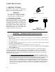
SAFETY PRECAUTIONS 1.2 EMERGENCY SHUTDOWN If overheating occurs or the gas supply fails to shut off, close the manual gas shutoff valve (Figure 1-1) located external to the unit. IMPORTANT MANUAL GAS SHUTOFF VALVE The Installer must identify and indicate the location of the emergency shutdown manual gas valve to operating personnel. 1.
SAFETY PRECAUTIONS Extracted Information From 248 CMR 5.08 (2) – Continued a. In the event that the side wall horizontally vented gas fueled equipment is installed in a crawl space or an attic, the hard wired carbon monoxide detector with alarm and battery back-up may be installed on the next adjacent floor level. b.
INSTALLATION CHAPTER 2 INSTALLATION 2.1 INTRODUCTION • Pressure/Temperature Gauge This Chapter provides the descriptions and procedures necessary to unpack, inspect and install the AERCO Benchmark 2.0 Low NOx (LN) Boiler. Brief descriptions are also provided for each available mode of operation. Detailed procedures for implementing these modes are provided in Chapter 5. • Spare Spark Igniter 2.
INSTALLATION 18" 44.5" 24" 79" 101" 30" 24" 24" REAR FRONT 4" HIGH PAD Figure 2-1 Benchmark 2.0LN Boiler Clearances WARNING KEEP THE UNIT AREA CLEAR AND FREE FROM ALL COMBUSTIBLE MATERIALS AND FLAMMABLE VAPORS OR LIQUIDS. CAUTION USE THE TABS SHOWN IN FIGURE 2-2 TO LIFT AND MOVE THE UNIT. Remove the top panel from the unit to provide access to the lifting tabs. Remove the four (4) lag screws securing the unit to the shipping skid.
INSTALLATION In multiple unit installations, it is important to plan the position of each unit in advance. Sufficient space for piping connections and future service/maintenance requirements must also be taken into consideration. All piping must include ample provisions for expansion. provided on the exhaust manifold as shown in Figure 2-4.
INSTALLATION fittings. Piping must be supported from the floor, ceiling or walls only and must not be supported by the unit. A suitable piping compound, approved for use with natural gas, should be used. Any excess must be wiped off to prevent clogging of components. To avoid unit damage when pressure testing gas piping, isolate the unit from the gas supply piping. At no time should the gas pressure applied to the unit exceed 2 psi.
INSTALLATION 2.7.3 IRI Gas Train Kit The IRI gas train is an optional gas train configuration which is required in some areas for code compliance or for insurance purposes. The IRI gas train is factory pre-piped and wired. See Appendix F, Drawing AP-A-843 for details. 2.8 AC ELECTRICAL POWER WIRING The AERCO Benchmark 2.0LN Electrical Power Wiring Guide, GF-2060LN, must be consulted prior to connecting any AC power wiring to the unit.
INSTALLATION In addition to the terminal strips shown in Figure 2-9, the I/O Box also contains a pre-wired temperature transmitter which receives inlet air temperature sensor readings and transmits this signal to the variable frequency drive (VFD) contained in the Boiler. The VFD utilizes this input signal to adjust the rotation speed of the blower. Brief descriptions of each mode of operation, and their wiring requirements, are provided in the following paragraphs.
INSTALLATION 2.9.2 Indoor/Outdoor Reset Mode This mode of operation increases supply water temperature as outdoor temperatures decrease. An outside air temperature sensor (AERCO Part No. 122790) is required. The sensor MUST BE wired to the I/O Box wiring terminals (see Figure 2-10). Refer to paragraph 2.10.1 for additional information on outside air temperature sensor installation. 2.9.
INSTALLATION 2-9 and 2-10). Wire the sensor using a twisted shielded pair wire from 18 to 22 AWG. There is no polarity to observe when terminating these wires. The shield is to be connected only to the terminals labeled SHIELD in the I/O Box. The sensor end of the shield must be left free and ungrounded. When mounting the sensor, it must be located on the North side of the building where an average outside air temperature is expected.
INSTALLATION described below, are factory wired in the closed position. NOTE Both the Delayed Interlock and Remote Interlock MUST be in the closed position to allow the unit to fire. 2.10.9.1 REMOTE INTERLOCK IN The remote interlock circuit is provided to remotely start (enable) and stop (disable) the Boiler, if desired. The circuit is labeled REMOTE INTL’K IN and is located inside the I/O Box on the front panel. The circuit is 24 VAC and is factory pre-wired in the closed (jumpered) position. 2.10.9.
INSTALLATION fired equipment. Common sources of these compounds are swimming pools, degreasing compounds, plastic processing and refrigerants. Whenever the environment contains these types of chemicals, combustion air must be supplied from a clean area outdoors for the protection and longevity of the equipment. The AERCO Benchmark 2.0LN Boiler is UL listed for 100% sealed combustion. It can also be installed using room air, provided there is an adequate supply. (See para. 2.13.
CONTROL PANEL OPERATING PROCEDURES CHAPTER 3 CONTROL PANEL OPERATING PROCEDURES 3.1 INTRODUCTION The information in this Chapter provides a guide to the operation of the Benchmark 2.0 Low NOx Boiler using the Control Panel mounted on the front of the unit. It is imperative that the initial startup of this unit be performed by factory trained personnel. Operation prior to initial startup by factory trained personnel will void the equipment warranty.
CONTROL PANEL OPERATING PROCEDURES Table 3-1 Operating Controls, Indicators and Displays ITEM NO. 1 CONTROL, INDICATOR OR DISPLAY LED Status Indicators FUNCTION Four Status LEDs indicate the current operating status as follows: COMM Lights when RS-232 communication is occurring MANUAL Lights when the unit is being controlled using the front panel keypad.
CONTROL PANEL OPERATING PROCEDURES Table 3-1 Operating Controls, Indicators and Displays – Continued ITEM NO. 10 11 CONTROL, INDICATOR OR DISPLAY MENU Keypad FUNCTION Consists of 6 keys which provide the following functions for the Control Panel Menus: MENU Steps through the main menu categories shown in Figure 32. The Menu categories wrap around in the order shown. BACK Allows you to go back to the previous menu level without changing any information.
CONTROL PANEL OPERATING PROCEDURES 3.3 CONTROL PANEL MENUS The Control Panel incorporates an extensive menu structure which permits the operator to set up, and configure the unit. The menu structure consists of four major menu categories as shown in Figure 3-2. Each of the menus shown, contain options which permit operating parameters to be viewed or changed. The menus are protected by a password to prevent unauthorized use.
CONTROL PANEL OPERATING PROCEDURES 3.4 OPERATING MENU The Operating Menu displays a number of key operating parameters for the unit as listed in Table 3-2. This menu is “Read-Only” and does not allow personnel to change or adjust any displayed items. Since this menu is “Read-Only”, it can be viewed at any time without entering a password. Pressing the ▲ arrow key to display the menu items in the order listed (Top-Down). Pressing the ▼ arrow key will display the menu items in reverse order (Bottom-Up). 3.
CONTROL PANEL OPERATING PROCEDURES 3.6 CONFIGURATION MENU NOTE The Configuration Menu shown in Table 3-4 permits adjustment of the Internal Setpoint (Setpt) temperature regardless of whether the valid password has been entered. Setpt is required for operation in the Constant Setpoint mode. The remaining options in this menu require the valid password to be entered, prior to changing existing entries.
CONTROL PANEL OPERATING PROCEDURES Table 3-4. Configuration Menu - Continued Available Choices or Limits Minimum Maximum Default Shutdown or Constant Setpt Shutdown *mA Output (See CAUTION) Setpoint, Outlet Temp, Fire Rate Out, Off *Fire Rate Out Low Fire Timer 2 sec. Menu Item Display Failsafe Mode 120 sec. Setpt Limiting Enabled or Disabled Setpt Limit Band 0°F 10°F 2 sec. Disabled 5°F *CAUTION: DO NOT CHANGE mA Output Menu Item from its Default setting.
CONTROL PANEL OPERATING PROCEDURES DIAL (DETAIL “A”) SSOV AIR IN TO AIR/FUEL VALVE TO BLOWER GAS INLET MANUAL SHUT-OFF VALVE 3. With all required safety device switches closed, a purge cycle will be initiated and the following events will occur: (a) The Blower Relay energizes and turns on Blower. (b) The Air/Fuel Valve rotates to the fullopen purge position and closes purge position switch. The dial on the Air/Fuel Valve (Figure 3-4) will read 100 to indicate that it is full-open (100%).
CONTROL PANEL OPERATING PROCEDURES AIR IN (a) The Air/Fuel Valve rotates to the lowfire ignition position and closes the ignition switch. The dial on the Air/Fuel Valve (Figure 3-6) will read between 25 and 35 to indicate that the valve is in the low-fire position. DIAL (DETAIL “A”) TO BLOWER 5. Upon completion of the purge cycle, the Control Box initiates an ignition cycle and the following events occur: (b) The igniter relay is activated and provides ignition spark.
CONTROL PANEL OPERATING PROCEDURES Table 3-6. Relationship Between Air/Fuel Valve Position and Energy Input For Unit Running On Natural Gas 3-10 Fire Rate, Air/Fuel Valve Position (% Open) Energy Input (BTU/Hr) Boiler Energy Input (% of Full Capacity) 0 0 0 10% 0 0 18% (Stop Level) 100,000 20% 134,000 7% 30% 349,000 17% 40% 631,000 32% 50% 893,000 45% 60% 1,150,000 58% 70% 1,410,000 71% 80% 1,610,000 81% 90% 1,830,000 92% 100% 2,000,000 100% 5.
INITIAL START-UP CHAPTER 4 4.1 INITIAL START-UP REQUIREMENTS The requirements for the initial start-up of the Benchmark 2.0 Low NOx (LN) Boiler consist of the following: • • • • • Complete installation Perform combustion calibration Set proper controls and limits Set up mode of operation (see Chapter 5) Test safety devices (see Chapter 6) Installation should be fully completed before performing initial start-up. The start-up must be complete prior to putting the unit into service.
INITIAL START-UP 5. Attach one end of the plastic tubing to the barbed fitting and the other end to the 16 inch W.C. manometer. SSOV GAS INLET HIGH GAS PRESSURE SWITCH 1/8" NPT PLUG (INSTALL MANOMETER HERE) LOW GAS PRESSURE SWITCH TO AIR/ FUEL VALVE MANUAL SHUT-OFF VALVE 4.3 NATURAL GAS COMBUSTION CALIBRATION The Benchmark 2.0LN Boiler is combustion calibrated at the factory prior to shipping.
INITIAL START-UP BRASS HEX HEAD CAP (REMOVE TO ACCESS DROOP ELIMINATOR ADJUSTMENT) TYPICAL SSOV ACTUATOR WITH DROOP ELIMINATOR AIR INLET IRIS AIR DAMPER (SEE VIEW “A”) Figure 4-3 Regulator Adjustment Screw Location 11. Raise the firing rate to 100% and verify that the gas pressure downstream of the SSOV remains at 2.8” W.C. Readjust pressure if necessary. 12.
INITIAL START-UP 21. If the oxygen level is not within the specified range, adjust the level using the up (Λ) and down (V) arrow keys on the VFD. Using the up (Λ) arrow key will increase oxygen level and the down (V) arrow key will decrease the oxygen level. 22. Once the oxygen level is within the specified range at 80%, lower the firing rate to 60% and select VFD parameter 64. The oxygen level at the 60% firing rate should be as shown below.
INITIAL START-UP Combustion Oxygen Level at 18% Firing Rate Oxygen % ± 0.2 8.0 % Carbon Monoxide <50 ppm NOx <30 ppm SEE DETAIL “A” 29. Adjust the oxygen level as necessary to obtain the required reading at the 18% firing rate. 30. This completes the Natural Gas combustion calibration procedures. 4.4 UNIT REASSEMBLY Once the combustion calibration adjustments are properly set, the unit can be reassembled for service operation. 1. Set the ON/OFF switch in the OFF position. 2.
MODE OF OPERATION CHAPTER 5 MODE OF OPERATION 5.1 INTRODUCTION The Benchmark 2.0 Low NOx (LN) Boiler is capable of being operated in any one of six different modes. The following paragraphs in this Chapter provide descriptions of each of these operating modes. Each Benchmark 2.0LN Boiler is shipped from the factory tested and configured for the ordered mode of operation. All temperature related parameters are at their factory default values which work well in most applications.
MODE OF OPERATION 7. Press the CHANGE key. The display will begin to flash. 8. Use the ▲ and ▼ arrow keys to select the desired Building Reference Temperature. 9. Press ENTER to save any changes. 5.4 REMOTE SETPOINT MODES The unit’s setpoint can be remotely controlled by an Energy Management System (EMS) or Building Automation System (BAS). The Remote Setpoint can be driven by a current or voltage signal within the following ranges: 10.
MODE OF OPERATION If the Network setting is selected for RS485 Modbus operation, a valid Comm Address must be entered in the Setup Menu. Refer to Modbus Communication Manual GF-114 for additional information. While it is possible to change the settings of temperature related functions, the unit is factory preset with settings that work well in most applications. It is suggested that an AERCO representative be contacted, prior to changing any temperature related function settings.
MODE OF OPERATION If the Network setting is selected for RS485 Modbus operation, a valid Comm Address must be entered in the Setup Menu. Refer to Modbus Communication Manual GF-114 for additional information. 5.5.1 Direct Drive Field Wiring The only wiring connections necessary for Direct Drive mode are connection of the remote signal leads from the source to the unit’s I/O Box. For either a 4-20mA/0-5V or a 0-20mA/0-5V setting, the connections are made at the ANALOG IN terminals in the I/O Box.
MODE OF OPERATION To change back to the BMS mode, simply press the AUTO/MAN switch. The REMOTE LED will again light and the MANUAL LED will go off. 5.7 COMBINATION CONTROL SYSTEM (CCS) NOTE Only BMS Model 168 can be utilized for the Combination Mode, not the BMS II (Model 5R5-384). A Combination Control System (CCS) is one that uses multiple boilers to cover both spaceheating and domestic hot water needs.
SAFETY DEVICE TESTING CHAPTER 6 SAFETY DEVICE TESTING 6.1 TESTING OF SAFETY DEVICES Periodic safety device testing is required to ensure that the control system and safety devices are operating properly. The Benchmark 2.0LN control system comprehensively monitors all combustion-related safety devices before, during and after the start sequence. The following tests check to ensure that the system is operating as designed.
SAFETY DEVICE TESTING 3. Slowly open the ball valve at the high gas pressure switch. 8. Open the water shut-off valve in the return piping to the unit. 4. Start the unit in Manual mode at a firing rate between 25 and 30%. 9. Open the water supply shut-off valve to the unit to refill. 5. Using a flat-tip screwdriver, slowly increase the gas pressure by turning the SSOV regulator adjustment screw clockwise. 6.
SAFETY DEVICE TESTING 6.6.1 REMOTE INTERLOCK 1. Remove the cover from the I/O Box and locate the REMOTE INTL’K IN terminals. 2. Start the unit in the Manual Mode and set the firing rate between 25% and 30%. SEE DETAIL “A” 3. If there is a jumper across the REMOTE INTL’K IN terminals, remove one side of the jumper. If the interlock is being controlled by an external device, either open the interlock via the external device or disconnect one of the wires leading to the external device. 4.
SAFETY DEVICE TESTING 4. Set the ON/OFF switch to the ON position to start the unit. 5. 5. The unit should shut down after reaching the Ignition cycle and display FLAME LOSS DURING IGN. 6. Next, check the Blocked Inlet Switch by closing the Iris Air Damper (Figure 4-4) to position 8. 6. Open the valve previously closed in step 3 and press the CLEAR button. 7. .The unit should shut down and again display AIRFLOW FAULT DURING RUN. 7. Restart the unit and allow it to prove flame. 8.
SAFETY DEVICE TESTING 3. Remove the Air/Fuel Valve cover (Figure 6-5) by rotating the cover counterclockwise to unlock and lift up to remove. 4. Remove one of the two wires (#169 or #170) from the Ignition Switch (Figure 6-6). 5. Initiate a unit start sequence. 6. The unit should begin it’s start sequence and then shut down and display IGN SWITCH OPEN DURING IGNITION. 7. Replace the wire on the Ignition Switch and press the CLEAR button. The unit should restart. Figure 6-4 SSOV Actuator Cover Location 6.
2 17 16 9 SAFETY DEVICE TESTING Figure 6-6 Air/Fuel Valve Purge and Ignition Switch Locations 6.12 SAFETY PRESSURE RELIEF VALVE TEST Test the safety Pressure Relief Valve in accordance with ASME Boiler and Pressure Vessel Code, Section VI.
MAINTENANCE CHAPTER 7 MAINTENANCE The unit requires regular routine maintenance to keep up efficiency and reliability. For best operation and life of the unit, the following routine maintenance procedures should be carried out in the time periods specified in Table 7-1. See Appendix I for a complete CSD-1 inspection check list. 5. The igniter is gapped at 1/8-inch. If there is a substantial erosion of the spark gap or ground electrode, the igniter should be replaced.
MAINTENANCE Table 7-1 - Maintenance Schedule PARAGRAPH 7.2 7.3 7.4 7.5 7.6 7.7 ITEM Spark Igniter (GP-122435-S) Flame Detector (66006) Combustion Calibration 6 Mos. 12 Mos. 24 Mos. Labor Time *Inspect Inspect Replace 15 mins. *Inspect Inspect Replace 15 mins. *Check Check 1 hr. See CSD-1 Chart in Appendix I 20 mins. Testing of Safety Devices Burner Condensate Drain Trap Inspect *Inspect Inspect & Clean 2 hrs. 15 mins.
MAINTENANCE 7.6 BURNER ASSEMBLY The burner assembly is located at the top of the unit. The burner assembly may be HOT. Allow the unit to cool sufficiently before removing the burner assembly. It should be noted that the complete burner assembly also includes the blower and air/fuel valve in addition to the Benchmark 2.0 Low NOx burner. It can be removed as one complete assembly. The following parts will be necessary for reassembly after inspection: Part No.
7.7 CONDENSATE DRAIN TRAP 7.8 SHUTTING THE BOILER DOWN FOR AN EXTENDED PERIOD OF TIME The Benchmark 2.0LN Boiler contains a condensate trap as shown in Figure 2-5. The trap is located external to the unit and attached to the drain pipe from the exhaust manifold. This traps should be inspected and, if necessary, cleaned to ensure proper operation.
TROUBLESHOOTING Chapter 8- TROUBLESHOOTING GUIDE 8.1 INTRODUCTION This troubleshooting guide is intended to aid service/maintenance personnel in isolating the cause of a fault in a Benchmark 2.0 Boiler. The troubleshooting procedures contained herein are presented in tabular form on the following pages. These tables are comprised of three columns labeled: Fault Indication, Probable Cause and Corrective Action. The numbered items in the Probable Cause and Corrective Action columns correspond to each other.
TROUBLESHOOTING TABLE 8-1. BOILER TROUBLESHOOTING FAULT INDICATION PROBABLE CAUSES TROUBLESHOOTING/CORRECTIVE ACTION AIRFLOW FAULT DURING IGNITION 1. Blower stopped running due to thermal or current overload 2. Blocked Blower inlet or inlet ductwork 1. Check combustion blower for signs of excessive heat or high current drain that may trip thermal or current overload devices. 2. Inspect the inlet to the combustion blower including any ductwork leading up to the combustion blower for signs of blockage.
TROUBLESHOOTING TABLE 8-1. BOILER TROUBLESHOOTING – Continued FAULT INDICATION (continued) AIRFLOW FAULT DURING PURGE PROBABLE CAUSES 16. VFD is not starting or is faulting. 1. Blower not running or running too slow 2. Defective Air Flow Switch 3. Blocked Air flow Switch 4. Blocked Blower inlet or inlet ductwork. AIRFLOW FAULT DURING RUN 16. See Table 8-4 for VFD parameter settings and Table 8-5 for VFD faults. 1. Start the unit.
TROUBLESHOOTING TABLE 8-1. BOILER TROUBLESHOOTING – Continued FAULT INDICATION DELAYED INTERLOCK OPEN DIRECT DRIVE SIGNAL FAULT FLAME LOSS DURING IGN PROBABLE CAUSES 1. Delayed Interlock Jumper not installed or removed. 2. Device proving switch hooked to interlocks is not closed 1. Direct drive signal is not present: Not yet installed. Wrong polarity. Signal defective at source. Broken or loose wiring. 2. Signal is not isolated (floating). 3.
TROUBLESHOOTING TABLE 8-1. BOILER TROUBLESHOOTING – Continued FAULT INDICATION (continued) FLAME LOSS DURING RUN HEAT DEMAND FAILURE HIGH GAS PRESSURE PROBABLE CAUSES 8. Defective staged ignition solenoid valve. 9. Clogged staged ignition piece. 8. When boiler goes to ignition, listen to solenoid valve to ensure it is opening. 9. Remove and inspect staged ignition piece for blockage. 10. Carbon or other debris on burner 10. Remove the burner and inspect for any carbon or debris.
TROUBLESHOOTING TABLE 8-1. BOILER TROUBLESHOOTING – Continued FAULT INDICATION HIGH WATER TEMP SWITCH OPEN PROBABLE CAUSES 1. Faulty Water temperature switch. 2. Incorrect PID settings. 3. Faulty shell temperature sensor. 4. Unit in Manual mode 5. Unit setpoint is greater than Over Temperature Switch setpoint. 6. Boiler Management System PID or other settings not correctly setup. 7. No interlock to boiler or BMS to disable boiler(s) in event that system pumps have failed. 8.
TROUBLESHOOTING TABLE 8-1. BOILER TROUBLESHOOTING – Continued FAULT INDICATION IGN SWTCH CLOSED DURING PURGE PROBABLE CAUSES 1. Air/Fuel Valve not rotating 2. Defective or shorted switch 3. Switch wired incorrectly 4. Defective Power Supply Board or fuse 5. Defective IGST Board IGN SWTCH OPEN DURING IGNITION 1. Air/Fuel Valve not rotating to ignition position. 2. Defective ignition switch 3. Defective Power Supply Board or fuse 4. Defective IGST Board INTERLOCK OPEN 8-7 1.
TROUBLESHOOTING TABLE 8-1. BOILER TROUBLESHOOTING – Continued FAULT INDICATION continued LINE VOLTAGE OUT OF PHASE LOW GAS PRESSURE PROBABLE CAUSES 3. Device proving switch hooked to interlocks is not closed. 1. Line and Neutral switched in AC Power Box. 2. Incorrect power supply transformer wiring. 1. Incorrect supply gas pressure. 2. Defective Low Pressure Gas Switch LOW WATER LEVEL 1. Insufficient water level in system 2. Defective water level circuitry. 3. Defective water level probe.
TROUBLESHOOTING TABLE 8-1. BOILER TROUBLESHOOTING – Continued FAULT INDICATION PRG SWTCH OPEN DURING PURGE PROBABLE CAUSES 1. Defective purge switch. 2. No voltage present at switch. 3. Switch wired incorrectly. 4. Defective Power Supply Board or fuse 5. Defective IGST Board OUTDOOR TEMP SENSOR FAULT 1. Loose or broken wiring. 2. Defective Sensor. 3. Incorrect Sensor. REMOTE SETPT SIGNAL FAULT RESIDUAL FLAME TROUBLESHOOTING/CORRECTIVE ACTION 1.
TROUBLESHOOTING TABLE 8-1. BOILER TROUBLESHOOTING – Continued FAULT INDICATION (continued) SSOV FAULT DURING PURGE SSOV FAULT DURING RUN SSOV RELAY FAILURE SSOV SWITCH OPEN PROBABLE CAUSES 2. Defective Flame Detector 3. 1. SSOV switch closed for 15 seconds during run. 1. Replace or adjust microswitch in SSOV actuator. If fault persists, replace actuator. 1. SSOV relay failed on board. 1. Press CLEAR button and restart unit. If fault persists, replace Ignition/Stepper (IGST) Board. 1.
TROUBLESHOOTING 8.2 ADDITIONAL FAULTS WITHOUT SPECIFIC FAULT MESSAGES Refer to Table 8-2 to troubleshoot faults which may occur without a specific fault message being displayed. TABLE 8-2. BOILER TROUBLESHOOTING WITH NO FAULT MESSAGE DISPLAYED OBSERVED INCIDENT Hard Light-Off Fluctuating Gas Pressure Air/Fuel Valve “hunting” at 80% Firing Rate 8-11 PROBABLE CAUSES 1. Staged Ignition Ball Valve closed. 2. Clogged/damaged Gas Injector (Figure 8-2). 3.
TROUBLESHOOTING HIGH GAS PRESSURE SWITCH TO AIR/FUEL VALVE SSOV SNUBBER LOW GAS PRESSURE SWITCH MANUAL SHUT-OFF VALVE GAS INLET STAGED IGNITION LINE BALL VALVE Figure 8-1 High Pressure Gas Switch & Snubber Locations Figure 8-2 Staged Ignition Solenoid Location 8-12 Figure 8-3 Damping Orifice Location Figure 8-4 VFD Terminal Locations
TROUBLESHOOTING Table 8-3 BMK 2.0 LN (3.3 KΩ) Temperature Sensor and Temperature Transmitter Outputs TEMP ºC TEMP ºF UA33 Resistance Ohm Volts outputs UA33 TEMP ºC TEMP ºF UA33 Resistance Ohm Volts outputs UA33 -40 -30 -20 -10 -5 0 1 2 3 4 5 6 7 8 9 10 11 12 13 14 15 16 17 18 19 20 21 22 23 24 25 26 27 -40 -22 -4 14 23 32 33.8 35.6 37.4 39.2 41 42.8 44.6 46.4 48.2 50 51.8 53.6 55.4 57.2 59 60.8 62.6 64.4 66.2 68 69.8 71.6 73.4 75.2 77 78.8 80.
TROUBLESHOOTING Table 8-4. VFD Parameter Settings VFD Parameter Parameter Value 1 2 5 10 19 59 61 62 63 64 65 71 72 73 74 75 0.0 100.0 AI.AV L3 Between -70.0 & 100.0 1 Between -150 & 250 Between 200 & 500 Between 250 & 600 Between 250 & 700 Between 400 & 850 18.20 18.21 18.22 18.23 18.24 • If a parameter value differs from the one shown in Table 8-4, reset the parameter to the value shown in the Table.
TROUBLESHOOTING 16. Shut down VFD power. 17. Turn On VFD power. 18. Set Pr. 59 to 1 19. Recalibrate the boiler using the combustion calibration procedures in Chapter 4. Table 8-5. VFD Faults NOTE Check parameters 55, 56, 57, & 58 for the last 4 Trips. VFD Fault Possible Cause UU Low AC supply voltage OU High AC supply voltage O.ht2 High ambient temperature CL1 Analog input loss (4-20 mA Air/Fuel Valve position signal) EEF Possible loss of parameters values C.
APPENDIX A APPENDIX A - BOILER MENU ITEM DESCRIPTIONS MENU LEVEL & OPTION DESCRIPTION OPERATING MENU Active Setpoint This is the setpoint temperature to which the control is set when operating in the Constant Setpoint, Remote Setpoint or Outdoor Reset Mode. When in the Constant Setpoint Mode, this value is equal to the Internal Setpoint setting in the Configuration Menu. When in the Remote Setpoint Mode, this value is the setpoint equivalent to the remote analog signal supplied to the unit.
APPENDIX A APPENDIX A - BOILER MENU ITEM DESCRIPTIONS - Continued MENU LEVEL & OPTION DESCRIPTION SETUP MENU Password Allows password to be entered. Once the valid password (159) is entered, options in the Setup, Configuration and Tuning Menus can be modified. Language Permits selection of English, Spanish or French for displayed messages. Default is English. Time Displays time from 12:00 am to 11:59 pm.
APPENDIX A APPENDIX A - BOILER MENU ITEM DESCRIPTIONS - Continued MENU LEVEL & OPTION DESCRIPTION Reset Ratio Permits setting of Reset Ratio when operating boiler in the Outdoor Reset Mode. Reset Ratio is adjustable from 0.1 to 9.9. Default is 1.2. Outdoor Sensor Allows outdoor sensor function to be enabled or disabled. Default is disabled. System Start Tmp If outdoor sensor is enabled, this menu item allows the system start temperature to be set from 30 to 100°F. Default is 60°F.
APPENDIX A APPENDIX A - BOILER MENU ITEM DESCRIPTIONS - Continued MENU LEVEL & OPTION DESCRIPTION TUNING MENU A-4 Prop Band Generates a fire rate based on the error that exists between the setpoint temperature and the actual outlet temperature. If the actual error is less than the proportional band setting (1 to 120°F), the fire rate will be less than 100%. If the error is equal to or greater than the proportional band setting, the fire rate will be 100%.
APPENDIX B APPENDIX B - STARTUP, STATUS AND FAULT MESSAGES TABLE B-1. STARTUP AND STATUS MESSAGES MESSAGE DISABLED HH:MM pm MM/DD/YY STANDBY DEMAND DELAY XX sec PURGING XX sec IGNITION TRIAL XX sec FLAME PROVEN WARMUP XX sec WAIT DESCRIPTION Displayed if ON/OFF switch is set to OFF. The display also shows the time and date that the unit was disabled. Displayed when ON/OFF switch is in the ON position, but there is no demand for heat. The time and date are also displayed.
APPENDIX B TABLE B-2.
APPENDIX B TABLE B-2. FAULT MESSAGES - Continued FAULT MESSAGE RESIDUAL FLAME HEAT DEMAND FAILURE IGN BOARD COMM FAULT DIRECT DRIVE SIGNAL FAULT REMOTE SETPT SIGNAL FAULT OUTDOOR TEMP SENSOR FAULT OUTLET TEMP SENSOR FAULT FFWD TEMP SENSOR FAULT HIGH WATER TEMPERATURE LINE VOLTAGE OUT OF PHASE STEPPER MOTOR FAILURE NETWORK COMM FAULT FAULT DESCRIPTION The Flame signal was seen for more than 60 seconds during standby. The Heat Demand Relays on the Ignition board failed to activate when commanded.
APPENDIX C TEMPERATURE SENSOR RESISTANCE CHART (BALCO) TEMPERATURE SENSOR AERCO PART NO. 123449 R = RESISTANCE (OHMS) T = TEMPERATURE (°F) R=.00161T^2+1.961T+854.841 TEMP (°F) RES. (OHMS) -40 779.0 -30 797.5 -20 816.3 -10 835.4 0 854.8 10 874.6 20 894.7 30 915.1 40 935.9 50 956.9 60 978.3 70 1000.0 80 1022.0 90 1044.4 100 1067.0 110 1090.0 120 1113.3 130 1137.0 140 1160.9 150 1185.2 160 1209.5 170 1234.7 180 1260.0 190 1285.6 200 1311.4 210 1337.7 220 1364.2 230 1391.0 240 1418.2 250 1445.
APPENDIX D APPENDIX D. - INDOOR/OUTDOOR RESET RATIO CHARTS Table D-1. Header Temperature for a Building Reference Temperature of 50F RESET RATIO Air Temp 0.6 0.8 1.0 1.2 1.4 1.6 1.8 2.0 2.2 2.
APPENDIX D Table D-3. Header Temperature for a Building Reference Temperature of 65F RESET RATIO Air Temp 0.6 0.8 1.0 1.2 1.4 1.6 1.8 2.0 2.2 2.
APPENDIX D Table D-5. Header Temperature for a Building Reference Temperature of 75F RESET RATIO Air Temp 0.6 0.8 1.0 1.2 1.4 1.6 1.8 2.0 2.2 2.
APPENDIX D Table D-7. Header Temperature for a Building Reference Temperature of 90F RESET RATIO Air Temp 0.6 0.8 1.0 1.2 1.4 1.6 1.8 2.0 2.2 2.
APPENDIX E BOILER DEFAULT SETTINGS MENU & OPTION FACTORY DEFAULT Setup Menu Password 0 Language English Unit of Temp Comm Address Baud Rate Fahrenheit 0 9600 Configuration Menu Internal Setpt 130°F Unit Type Boiler Unit Size 1.5 MBTU Boiler Mode Constant Setpoint Remote Signal (If Mode = Remote Setpoint, Direct Drive or Combination) 4 – 20 mA / 1-5V Bldg Ref Temp (If Boiler Mode = Outdoor Reset) 70°F Reset Ratio (If Boiler Mode = Outdoor Reset) 1.
210 160 240 TEST PRESS. (PSIG) 56 (142.2) 13-1/4 (33.7) 12-3/4 (32.4) (17.8) 7.00 7-3/4 (19.7) 8" EXHAUST OUTLET 1-1/2" NPT DRAIN CONN. 23-1/2 (59.7) (60.3) 23-3/4 87 HT'G SURFACE SQ.FT. 50-3/4 (128.9) 1-1/4 (3.2) 2-1/2 (6.4) CONDENSATE DRAIN 15 (38.1) 4"-150# FLG'D COLD WATER INLET CONN. 2" NPT GAS INLET CONN. PRESS./TEMP. GAUGE 7-1/2 (19.1) 79 (200.7) 28 (71.1) DWN.BY JK SCALE CHKD. REV.DATE DATE 092608 SIZE APPD. AP-A-798 BENCHMARK 2 MIL.
F-2 2) ALL DIMENSIONS SHOWN ARE IN INCHES (CENTIMETERS) NOTES: 1) ALL HOLES ARE FLUSH WITH THE BOTTOM SURFACE OF THE FRAME FRONT INTERNATIONAL, INC. NORTHVALE, NJ 07647 *NOT TO SCALE* DRWN BY:SJD DATE:10/12/07 REV SD - A - 730 B BENCHMARK 1.5 / 2.
ENTIRE BMK2.0 LN FM GAS TRAIN P/N: 22064-1 2" - SCH. 40 PIPE LOW GAS PRESSURE SWITCH P/N: 61002-1 HIGH GAS PRESSURE SWITCH P/N: 61002-12 FULL PORT BALL VALVE 1.50" NPT P/N: 92006-7 TO A/F VALVE ASSY. TEST COCK INTERNATIONAL, INC. NORTHVALE, NJ 07647 *NOT TO SCALE* DRWN BY:SJD DATE:2/12/09 REV AP - A – 842-M A BENCHMARK 2.0 LOW NOx FM GAS TRAIN AERCO 1/8" NPT PLUG (INSTALL MANOMETER HERE) GAS PRESSURE SNUBBER P/N: 99017 1.
F-4 2" SCH.40 PIPE 1.5" SSOV VALVE BODY P/N: 124150 3/4" SCH.40 PIPE VENT TO ATMOSPHERE PER ANSI Z223.1 (NFPA54) ENTIRE BMK2.0 LN IRI GAS TRAIN P/N: 22064-2 SAFETY SHUT OFF VALVE ACTUATOR WITHOUT PROOF OF CLOSURE SWITCH P/N: 69038 1.5" SAFETY SHUT OFF VALVE BODY P/N: 124150 1/8" NPT PLUG (INSTALL MANOMETER HERE) TEST COCK LOW GAS PRESSURE SWITCH P/N: 61002-1 SAFETY SHUT OFF VALVE ACTUATOR W/DROOP ELIMINATOR, P/N: 64048 NORMALLY OPEN VENT VALVE P/N: GP-122774 INTERNATIONAL, INC.
APPENDIX F F-5
APPENDIX F EXHAUST MANIFOLD ITEM PART NO. QTY DESCRIPTION 201283 123612 EXHAUST MANIFOLD EXHAUST MANIFOLD SEAL 1 2 3 1 1 HOSES,GASKETS, & INSULATION ITEM PART NO. QTY 25 (1) 26 27 88003 62005 1 1 DESCRIPTION O-RING #2-339 (A/F VALVE) CORD GRIP 28 29 GAS TRAIN ASSEMBLY ITEM PART NO. 22064-1 22064-2 (3) 4 QTY 1 DESCRIPTION STD FM GAS TRAIN ASSY IRI GAS TRAIN ASSY DUAL FUEL FM GAS TRAIN DUAL FUEL IRI GAS TRAIN BURNER & AIR/FUEL VALVE ITEM PART NO.
APPENDIX F OTHER DUAL FUEL COMPONENTS CONTROLS ITEMPART NO. QTY DESCRIPTION 30 31 32 33 34 123966 123552 61002-5 60011 161560 1 1 1 1 1 35 181197-1 1 36 37 38 39 40 GP-122464 33048 64054 61012 64018 1 1 1 1 1 (1) 41 IGNITION CABLE ASSY. 42 43 44 GP-122569 63016 63038 63042 1 (1) (1) (1) 1 1 1 BMK2.
APPENDIX F F-8
APPENDIX F B 21 52 14 33 51 32 6 8 60 16 AERCO NORTHVALE, NJ 07647 INTERNATIONAL, INC. 25 DETAIL B BENCHMARK 2.
APPENDIX F F-10
APPENDIX F 73 74 75 71 72 AERCO INTERNATIONAL, INC. NORTHVALE, NJ 07647 BENCHMARK 2.
APPENDIX F F-12
1-1/2" NPT DRAIN CONN. SYSTEM PUMP * CONDENSATE DRAIN TRAP AIR SEPARATOR AUTOMATIC AIR VENT P&T RELIEF VALVE (TYP.) 7) A GAS REGULATOR IS MANDATORY FOR THE STATE OF MASSACHUSETTS, REGARDLESS OF SUPPLY PRESSURE. SEE DIAGRAM 1 BE 6'' AWAY FROM SIDE PANELS. 5) THIS IS A TYPICAL INSTALLATION DRAWING. LOCAL CODES AND AUTHORITIES SHOULD BE CONSULTED. 6) WHEN AVAILABLE GAS PRESSURE IS GREATER THAN 2.
G-2 1-1/2" NPT DRAIN CONN. SYSTEM PUMP * CONDENSATE DRAIN TRAP AIR SEPARATOR AUTOMATIC AIR VENT P&T RELIEF VALVE (TYP.) FREELY, BY GRAVITY, TO A CONVENIENT FLOOR DRAIN. RELIEF VALVE SHOULD BE PIPED VERTICALLY TO A SEE DIAGRAM 1 7) A GAS REGULATOR IS MANDATORY FOR THE STATE OF MASSACHUSETTS, REGARDLESS OF SUPPLY PRESSURE. 6) WHEN AVAILABLE GAS PRESSURE IS GREATER THAN 2.0 PSIG, A LOCK-UP STYLE REGULATOR MUST BE INSTALLED DOWNSTREAM OF THE 2" MANUAL SHUTOFF VALVE TO BRING THE GAS PRESSURE DOWN TO 2.
* 2" MANUAL SHUTOFF VALVE DRIP TRAP GAS SUPPLY AUTOMATIC AIR VENT P&T AIR SEPARATOR * CONDENSATE DRAIN TRAP 1-1/2" NPT DRAIN CONN. SYSTEM PUMP P&T P&T RELIEF VALVE (TYP.) 7) A GAS REGULATOR IS MANDATORY FOR THE STATE OF MASSACHUSETTS, REGARDLESS OF SUPPLY PRESSURE. SEE DIAGRAM 1 6) WHEN AVAILABLE GAS PRESSURE IS GREATER THAN 2.0 PSIG, A LOCK-UP STYLE REGULATOR MUST BE INSTALLED DOWNSTREAM OF THE 2" MANUAL SHUTOFF VALVE TO BRING THE GAS PRESSURE DOWN TO 2.0 PSIG.
APPENDIX G G-4
APPENDIX H H-1
J1 1 2 232 3 233 4 237 7 236 6 235 5 234 7 8 231 1 OUTDOOR AIR SENSOR IN 2 SENSOR COMMON IN 3 AUX SENSOR IN 5 - 4 + CO SENSOR IN 6 + 8 238 8 240 241 242 243 244 245 246 2 1 247 3 251 4 250 5 252 6 253 8 7 254 13 14 15 16 17 18 19 20 21 22 23 24 9 10 11 12 13 14 15 239 9 10 11 12 24-PIN CONNECTOR 11 6 15 5 - 7 FLOW SENSOR IN 9 + OXYGEN SENSOR IN - 10 SENSOR EXCIT.
APPENDIX H H-3
5 8 12 11 9 10 11 12 13 14 15 13 J1 7 6 6 5 4 1 2 1 15 3 232 234 240 242 244 246 236 238 233 241 243 245 247 235 237 239 9 3 4 2 3 4 5 6 8 7 250 252 254 251 253 9 10 11 12 13 14 15 16 17 18 19 20 21 22 23 24 231 1 2 OUTDOOR AIR SENSOR IN SENSOR COMMON IN 7 AUX SENSOR IN 8 + CO SENSOR IN + FLOW SENSOR IN + OXYGEN SENSOR IN - 10 SENSOR EXCIT.
APPENDIX I RECOMMENDED PERIODIC TESTING CHECK LIST WARNING NOTE: Periodic testing of all boiler controls and safety devices is required to determine that they are operating as designed. Precautions shall be taken while tests are being performed to protect against bodily injury and property damage. The owner or user of an automatic boiler system should set up a formal system of periodic preventive maintenance and testing. Tests should be conducted on a regular basis and the results recorded in a log-book.
APPENDIX J BENCHMARK CONTROL PANEL EXPLODED VIEW J-1
P1 P2 P3 P4 P5 P6 APPENDIX J BENCHMARK CONTROL PANEL REAR VIEW J-2
Standard Warranty: Benchmark Gas-Fired Hydronic Boiler International, Inc. PRESSURE VESSEL/HEAT EXCHANGER: 10 YEARS FROM SHIPMENT The pressure vessel/heat exchanger shall carry a 10-year prorated, limited warranty from shipment against any failure due to condensate corrosion, thermal stress, mechanical defects or workmanship. Operation of the boiler using contaminated air will void the warranty.
Standard Warranty: Benchmark Gas-Fired Hydronic Boiler International, Inc. CONDITIONS OF WARRANTY Should an AERCO gas-fired Hydronic boiler fail for any of the above reasons within the specified time period from the date of original shipment(s), AERCO shall, at its option, modify, repair or exchange the defective item. AERCO shall have the option of having the item returned, FOB its factory, or to make field replacements at the point of installation.