
Owner manual

CHAPTER 3: CONTROL PANEL OPERATION
PR2: 04/22/13 Page 35 of 160
Benchmark 2.0LN Dual-Fuel Low NOx Boiler
Operation and Maintenance Manual
OMM-0052_0E
GF-127
AERCO International, Inc. • 100 Oritani Dr. • Blauvelt, NY 10913 • Ph: 800-526-0288
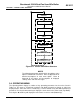
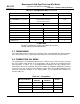
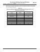
Table 3-4: Configuration Menu (Continued)
Aux Start On Dly 0 sec. 120 sec. 0 sec.
Failsafe Mode Shutdown or Constant Setpt Shutdown
*Analog Output
(See CAUTION at end of Table
3-4 )
Off, Setpoint, Outlet Temp,
Valve Position 4-20 mA,
Valve Position 0-10V
*Valve Position
0-10V
Low Fire Timer 2 sec. 600 sec. 2 sec.
Setpt Limiting Enabled or Disabled Disabled
Setpt Limit Band 0°F 10°F 5°F
Network Timeout 5 Sec 999 Sec 30 Sec
HI DB Setpt EN 0% 100% 30%
Demand Offsert 0 25 10
Deadband High 0 25 2
Deadband Low 0 25 2
*CAUTION!
DO NOT CHANGE the Analog Output Menu Item from its
Default setting (Valve Position 0-10V).
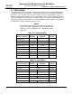
3.7 TUNING MENU
The Tuning Menu items in Table 3-5 are Factory set for each individual unit. Do not change
these menu entries unless specifically requested to do so by Factory-Trained personnel.
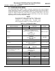
3.8 COMBUSTION CAL MENU
The Combustion Cal (Calibration) Menu items in Table 3-6 are used to vary the speed of
the unit’s blower motor based on air temperature and air density at prescribed Air/Fuel
Valve positions (% open). This is accomplished by providing a DC drive voltage to the
motor which adjusts the rotational speed of the blower to maximize combustion efficiency
and ensure the unit conforms to the Nitrogen Oxide (NOx) and Carbon Monoxide (CO)
emissions specified in Chapter 4. The valve positions (%) and default drive voltages are
listed in Table 3-6.
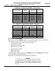
Table 3-5: Tuning Menu
Menu Item Display
Available Choices or Limits
Default
Minimum
Maximum
Prop Band 1°F 120°F 70°F
Integral Gain 0.00 2.00 1.00
Derivative Time 0.0 min 2.00 min 0.00 min
Reset Defaults? Yes, No, Are You Sure? No