Benchmark 2.0LN Dual-Fuel Low NOx Boiler GF-127 Operation and Maintenance Manual OMM-0052_0E Modulating, Condensing, Forced Draft, Hot Water Boiler 2,000,000 BTU/H Input Applicable for Serial Numbers: G-11-2402 and above. Benchmark 2.0LN Dual-Fuel Low NOx Boiler USER MANUAL Installation, Operation, and Maintenance Benchmark 2.0LN Low NOx Boiler Revised: 04/22/2013 PR2: 04/22/13 AERCO International, Inc. • 100 Oritani Dr.
Benchmark 2.0LN Dual-Fuel Low NOx Boiler Operation and Maintenance Manual GF-127 OMM-0052_0E Technical Support: (Mon–Fri, 8am-5pm EST) 1-800-526-0288 www.aerco.com Disclaimer The information contained in this manual is subject to change without notice from AERCO International, Inc. AERCO makes no warranty of any kind with respect to this material, including but not limited to implied warranties of merchantability and fitness for a particular application.
Benchmark 2.0LN Dual-Fuel Low NOx Boiler Operation and Maintenance Manual GF-127 OMM-0052_0E Table of Contents CHAPTER 1: SAFETY PRECAUTIONS .................................................................................. 9 1.1 WARNINGS & CAUTIONS .................................................................................... 9 1.2 EMERGENCY SHUTDOWN ............................................................................... 10 1.3 PROLONGED SHUTDOWN.............................................
Benchmark 2.0LN Dual-Fuel Low NOx Boiler Operation and Maintenance Manual GF-127 OMM-0052_0E 2.10.11 Interlocks (10, 12) ........................................................................................... 23 2.10.12 Fault Relay (13).................................................................................................. 24 2.10.13 Auxiliary Relay Contacts (14) ........................................................................... 24 2.11 FLUE GAS VENT INSTALLATION ...................
Benchmark 2.0LN Dual-Fuel Low NOx Boiler Operation and Maintenance Manual GF-127 OMM-0052_0E 5.3 CONSTANT SETPOINT MODE .......................................................................... 57 5.3.1 Setting the Setpoint .................................................................................................. 57 5.4 REMOTE SETPOINT MODES ............................................................................ 58 5.4.1 Remote Setpoint Field Wiring ..........................................
Benchmark 2.0LN Dual-Fuel Low NOx Boiler Operation and Maintenance Manual GF-127 OMM-0052_0E 7.8 SHUTTING THE BOILER DOWN FOR AN EXTENDED PERIOD OF TIME....... 81 7.9 PLACING THE BOILER BACK IN SERVICE AFTER A PROLONGED SHUTDOWN ............................................................................................................. 81 CHAPTER 8: TROUBLESHOOTING GUIDE ..................................................................... 83 8.1 INTRODUCTION..............................................
Benchmark 2.0LN Dual-Fuel Low NOx Boiler Operation and Maintenance Manual GF-127 OMM-0052_0E Foreword The AERCO Benchmark 2.0LN Dual-Fuel Low NOx (LN) Boiler is a modulating unit. It represents a true industry advance that meets the needs of today's energy and environmental concerns. Designed for application in any closed loop hydronic system, the Benchmark's modulating capability relates energy input directly to fluctuating system loads. The Benchmark 2.
Benchmark 2.0LN Dual-Fuel Low NOx Boiler Operation and Maintenance Manual GF-127 OMM-0052_0E (This page left intentionally blank) Page 8 of 160 AERCO International, Inc. • 100 Oritani Dr.
GF-127 Benchmark 2.0LN Dual-Fuel Low NOx Boiler Operation and Maintenance Manual CHAPTER 1: SAFETY PRECAUTIONS OMM-0052_0E CHAPTER 1: SAFETY PRECAUTIONS 1.1 WARNINGS & CAUTIONS Installers and operating personnel MUST, at all times, observe all safety regulations. The following warnings and cautions are general and must be given the same attention as specific precautions included in these instructions.
Benchmark 2.0LN Dual-Fuel Low NOx Boiler GF-127 Operation and Maintenance Manual CHAPTER 1: SAFETY PRECAUTIONS OMM-0052_0E WARNING electrical voltages up to 120 vac may be used in this equipment. Therefore the cover on the unit’s power box (located behind the front panel door) must be installed at all times, except during maintenance and servicing. CAUTIONS Must be observed to prevent equipment damage or loss of operating effectiveness.
GF-127 Benchmark 2.0LN Dual-Fuel Low NOx Boiler Operation and Maintenance Manual CHAPTER 2: INSTALLATION OMM-0052_0E CHAPTER 2: INSTALLATION 2.1 INTRODUCTION This Chapter provides the descriptions and procedures necessary to unpack, inspect and install the AERCO Benchmark 2.0LN Dual-Fuel Boiler. Brief descriptions are also provided for each available mode of operation. Detailed procedures for implementing these modes are provided in Chapter 5. 2.2 RECEIVING THE UNIT Each Benchmark 2.
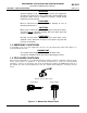
Benchmark 2.0LN Dual-Fuel Low NOx Boiler GF-127 Operation and Maintenance Manual CHAPTER 2: INSTALLATION OMM-0052_0E • Access to AC Input Power at 120 VAC, Single-Phase, 60 Hz @ 20 Amps • Access to Natural Gas line at a minimum supply gas pressure of 8.5" W.C. • Access to Propane line at a minimum supply gas pressure of 8.5” W.C. 2.4.1 Installation Clearances The unit must be installed with the prescribed clearances for service as shown in Figure 2-1.
GF-127 Benchmark 2.0LN Dual-Fuel Low NOx Boiler Operation and Maintenance Manual CHAPTER 2: INSTALLATION OMM-0052_0E locations. Two lifting tabs are provided at the top of the heat exchanger. Figure 2-2 shows the location of the tab on the top-left side. The second tab is located on the top-right side of the heat exchanger. USE THESE TWO TABS TO LIFT AND MOVE THE UNIT. Remove the top panel from the unit to provide access to the lifting tabs.
Benchmark 2.0LN Dual-Fuel Low NOx Boiler Operation and Maintenance Manual CHAPTER 2: INSTALLATION GF-127 OMM-0052_0E BOILER SUPPLY 4" – 150# FLANGE CONNECTION 2" PROPANE INLET CONNECTION 2" NATURAL GAS INLET CONNECTION SHELL DRAIN VALVE BOILER RETURN EXHAUST MANIFOLD REAR VIEW Figure 2-3: Supply and Return Locations 2.6 CONDENSATE DRAIN AND PIPING The Benchmark 2.0LN Boiler is designed to condense water vapor from the flue products.
Benchmark 2.0LN Dual-Fuel Low NOx Boiler GF-127 Operation and Maintenance Manual CHAPTER 2: INSTALLATION OMM-0052_0E BOILER RETURN EXHAUST MANIFOLD 1/2” NPT CONDENSATE DRAIN CONNECTION HOUSEKEEPING PAD Figure 2-4: Condensate Drain Connection Location 2.6.1 Exhaust Manifold Condensate Drain NOTE There are two slightly different types of condensate traps that may be used in your configuration; an older style without built-in adapter, and a newer style with a built-in adapter (see Figure 2-5).
Benchmark 2.0LN Dual-Fuel Low NOx Boiler GF-127 Operation and Maintenance Manual CHAPTER 2: INSTALLATION OMM-0052_0E Figure 2-5: Condensate Trap Installation: Older (left) and Newer (right) Style 2.7 GAS SUPPLY PIPING The AERCO Benchmark 2.0LN Gas Components and Supply Design Guide, GF-2030 must be consulted prior to designing or installing any gas supply piping. WARNING NEVER USE MATCHES, CANDLES, FLAMES OR OTHER SOURCES OF IGNITION TO CHECK FOR GAS LEAKS.
GF-127 Benchmark 2.0LN Dual-Fuel Low NOx Boiler Operation and Maintenance Manual CHAPTER 2: INSTALLATION OMM-0052_0E 2.7.1 Gas Supply Specifications. The maximum static pressure to the unit must not exceed 14” W.C. The specifications for natural gas and propane are as follows: Natural Gas: The gas supply pressure to the unit must be of sufficient capacity to provide 2000 cfh while maintaining the gas pressure at 4.0" W.C. for FM or 5.0" W.C. for IRI gas trains.
Benchmark 2.0LN Dual-Fuel Low NOx Boiler GF-127 Operation and Maintenance Manual CHAPTER 2: INSTALLATION OMM-0052_0E compliance or for insurance purposes. The IRI gas train is factory pre-piped and wired. See Appendix F, Drawing AP-A-843 for details. 2.8 AC ELECTRICAL POWER WIRING The AERCO Benchmark 2.0LN Electrical Power Wiring Guide, GF-2060LN, must be consulted prior to connecting any AC power wiring to the unit.
GF-127 Benchmark 2.0LN Dual-Fuel Low NOx Boiler Operation and Maintenance Manual CHAPTER 2: INSTALLATION OMM-0052_0E 120 VAC, 1 PHASE GND NEU L1 Figure 2-8: AC Terminal Block Configurations 2.9 MODES OF OPERATION AND FIELD CONTROL WIRING The Benchmark 2.0 Boiler is available in several different modes of operation. While each unit is factory configured and wired for its intended mode, some additional field wiring may be required to complete the installation.
Benchmark 2.0LN Dual-Fuel Low NOx Boiler GF-127 Operation and Maintenance Manual CHAPTER 2: INSTALLATION OMM-0052_0E 2.9.2 Indoor/Outdoor Reset Mode This mode of operation increases supply water temperature as outdoor temperatures decrease. An outside air temperature sensor (AERCO Part No. 122790) is required. The sensor MUST BE wired to the I/O Box wiring terminals (see Figure 2-10). Refer to paragraph 2.10.1 for additional information on outside air temperature sensor installation. 2.9.
GF-127 Benchmark 2.0LN Dual-Fuel Low NOx Boiler Operation and Maintenance Manual CHAPTER 2: INSTALLATION OMM-0052_0E applications), and the RS485 comm terminals in the I/O box. The wiring must be accomplished using twisted-shielded pair wire from 18 to 22 AWG. Polarity must be maintained. For further instructions and wiring diagrams, refer to the GF-108 Boiler Management System Operations Guide and the CCP-1 data sheet (BMS 168 applications)/GF-131 and TAG-0050 (ACS applications). Figure 2-10.
Benchmark 2.0LN Dual-Fuel Low NOx Boiler GF-127 Operation and Maintenance Manual CHAPTER 2: INSTALLATION OMM-0052_0E enable/disable outdoor temperature, see the Configuration menu in Chapter 3. The outdoor sensor may be wired up to 200 feet from the boiler. It is connected to the OUTDOOR SENSOR IN and SENSOR COMMON terminals in the I/O Box (see Figures 2-9 and 2-10). Wire the sensor using a twisted shielded pair wire from 18 to 22 AWG. There is no polarity to observe when terminating these wires.
GF-127 Benchmark 2.0LN Dual-Fuel Low NOx Boiler Operation and Maintenance Manual CHAPTER 2: INSTALLATION OMM-0052_0E 2.10.5 Shield (5) The SHIELD terminals are used to terminate any shields used on sensor wires connected to the unit. Only shields must be connected to these terminals. IMPORTANT DO NOT USE the mA OUT output to remotely monitor Setpoint, Outlet Temp or Fire Rate Out. 2.10.
Benchmark 2.0LN Dual-Fuel Low NOx Boiler GF-127 Operation and Maintenance Manual CHAPTER 2: INSTALLATION OMM-0052_0E If the delayed interlock is connected to a proving device that requires time to close (make), a time delay (Aux Start On Dly) that holds the start sequence of the boiler long enough for a proving switch to make can be programmed. Should the proving switch not prove within the programmed time frame, the boiler will shut down. The Aux Start On Dly can be programmed from 0 to 120 seconds.
Benchmark 2.0LN Dual-Fuel Low NOx Boiler GF-127 Operation and Maintenance Manual CHAPTER 2: INSTALLATION OMM-0052_0E information concerning combustion air, refer to the AERCO Benchmark Venting and Combustion Air Guide, GF-2050. 2.12.1 Combustion Air From Outside the Building Air supplied from outside the building must be provided through two permanent openings. Each opening must have a free area of not less than one square inch for each 4000 BTU/H boiler input.
Benchmark 2.0LN Dual-Fuel Low NOx Boiler GF-127 Operation and Maintenance Manual CHAPTER 2: INSTALLATION OMM-0052_0E If pump/valve load exceeds the above contact ratings, use a separate contact relay. See Diagrams 2-1a and 2-1b. To identify if the boiler is equipped with the BMK Pump Relay Option (part no. 69102), look for the label and relay as shown in Figure 2-12.
GF-127 Benchmark 2.0LN Dual-Fuel Low NOx Boiler Operation and Maintenance Manual OMM-0052_0E CHAPTER 3: CONTROL PANEL OPERATION 3.1 INTRODUCTION The information in this Chapter provides a guide to the operation of the Benchmark 2.0LN Boiler using the Control Panel mounted on the front of the unit. It is imperative that the initial startup of this unit be performed by factory trained personnel. Operation prior to initial startup by factory trained personnel will void the equipment warranty.
Benchmark 2.0LN Dual-Fuel Low NOx Boiler GF-127 Operation and Maintenance Manual CHAPTER 3: CONTROL PANEL OPERATION OMM-0052_0E 2 1 3 4 12 5 11 6 10 7 8 9 Figure 3-1: Control Panel Front View Page 28 of 160 AERCO International, Inc. • 100 Oritani Dr.
Benchmark 2.0LN Dual-Fuel Low NOx Boiler GF-127 Operation and Maintenance Manual CHAPTER 3: CONTROL PANEL OPERATION OMM-0052_0E Table 3-1 Operating Controls, Indicators and Displays ITEM NO. 1 CONTROL, INDICATOR OR DISPLAY LED Status Indicators FUNCTION Four Status LEDs indicate the current operating status as follows: COMM Lights when RS-232 communication is occurring MANUAL Lights when the unit is being controlled using the front panel keypad.
Benchmark 2.0LN Dual-Fuel Low NOx Boiler Operation and Maintenance Manual CHAPTER 3: CONTROL PANEL OPERATION GF-127 OMM-0052_0E Table 3-1 Operating Controls, Indicators and Displays (Continued) ITEM NO. CONTROL, INDICATOR OR DISPLAY MENU Keypad FUNCTION Consists of 6 keys which provide the following functions for the Control Panel Menus: MENU Steps through the main menu categories shown in Figure 3-2. The Menu categories wrap around in the order shown.
GF-127 Benchmark 2.0LN Dual-Fuel Low NOx Boiler Operation and Maintenance Manual CHAPTER 3: CONTROL PANEL OPERATION OMM-0052_0E 3.3 CONTROL PANEL MENUS The Control Panel incorporates an extensive menu structure which permits the operator to set up, and configure the unit. The menu structure consists of five major menu categories which are applicable to this manual. These categories are shown in Figure 3-2. Each of the menus shown, contain options which permit operating parameters to be viewed or changed.
Benchmark 2.0LN Dual-Fuel Low NOx Boiler Operation and Maintenance Manual CHAPTER 3: CONTROL PANEL OPERATION GF-127 OMM-0052_0E OPERATING LEVEL 1 PWD SETUP CONFIGURATION TUNING LEVEL 2 PWD COMBUSTION CAL CALIBRATION (NOT USED IN THIS O & M) DIAGNOSTICS (NOT USED IN THIS O & M) Figure 3-2: Control Panel Menu Structure NOTE The following paragraphs provide brief descriptions of the options contained in each menu. Refer to Appendix A for detailed descriptions of each menu option.
Benchmark 2.0LN Dual-Fuel Low NOx Boiler GF-127 Operation and Maintenance Manual CHAPTER 3: CONTROL PANEL OPERATION OMM-0052_0E 3.5 SETUP MENU The Setup Menu (Table 3-3) permits the operator to enter the unit password (159) which is required to change the menu options. To prevent unauthorized use, the password will timeout after 1 hour. Therefore, the correct password must be reentered when required.
Benchmark 2.0LN Dual-Fuel Low NOx Boiler Operation and Maintenance Manual CHAPTER 3: CONTROL PANEL OPERATION GF-127 OMM-0052_0E 3.6 CONFIGURATION MENU The Configuration Menu shown in Table 3-4 permits adjustment of the Internal Setpoint (Setpt) temperature regardless of whether the valid password has been entered. Setpt is required for operation in the Constant Setpoint mode. The remaining options in this menu require the valid password to be entered, prior to changing existing entries.
Benchmark 2.0LN Dual-Fuel Low NOx Boiler GF-127 Operation and Maintenance Manual CHAPTER 3: CONTROL PANEL OPERATION OMM-0052_0E Table 3-4: Configuration Menu (Continued) Aux Start On Dly 0 sec. 120 sec. 0 sec. Failsafe Mode Shutdown or Constant Setpt Shutdown *Analog Output (See CAUTION at end of Table 3-4 ) Off, Setpoint, Outlet Temp, Valve Position 4-20 mA, Valve Position 0-10V *Valve Position 0-10V Low Fire Timer 2 sec. Setpt Limiting 600 sec. 2 sec.
Benchmark 2.0LN Dual-Fuel Low NOx Boiler Operation and Maintenance Manual CHAPTER 3: CONTROL PANEL OPERATION GF-127 OMM-0052_0E Table 3-6: Combustion Cal Menu – Natural Gas Available Choices or Limits Menu Item Display Minimum Maximum Default CAL Voltage 20% .25 Vdc 10.0 Vdc 1.00 Vdc CAL Voltage 30% .25 Vdc 10.0 Vdc 2.30 Vdc CAL Voltage 45% .25 Vdc 10.0 Vdc 2.9 Vdc CAL Voltage 60% .25 Vdc 10.0 Vdc 3.60 Vdc CAL Voltage 80% .25 Vdc 10.0 Vdc 5.30 Vdc CAL Voltage 100% .25 Vdc 10.
Benchmark 2.0LN Dual-Fuel Low NOx Boiler GF-127 Operation and Maintenance Manual CHAPTER 3: CONTROL PANEL OPERATION OMM-0052_0E 1. 2. 3. The DEMAND LED status indicator will light. The unit checks to ensure that the Proof of Closure (POC) switch in the downstream Safety Shut-Off Valve (SSOV) is closed. Figure 3-3 shows the Natural Gas SSOV location for a Factory Mutual (FM) Gas Train.
Benchmark 2.0LN Dual-Fuel Low NOx Boiler Operation and Maintenance Manual CHAPTER 3: CONTROL PANEL OPERATION GF-127 OMM-0052_0E c) The gas Safety Shut-Off Valve (SSOV) is energized (opened) allowing gas to flow into the Air/Fuel Valve. AIR IN TO BLOWER DIAL (DETAIL “A”) STEPPER MOTOR 100 DETAIL “A” Figure 3-4: Air/Fuel Valve In Purge Position Figure 3-5: Blower Proof Switch Page 38 of 160 AERCO International, Inc. • 100 Oritani Dr.
Benchmark 2.0LN Dual-Fuel Low NOx Boiler GF-127 Operation and Maintenance Manual CHAPTER 3: CONTROL PANEL OPERATION OMM-0052_0E AIR IN TO BLOWER DIAL (DETAIL “A”) STEPPER MOTOR 25 DETAIL “A” Figure 3-6: Air/Fuel Valve In Ignition Position 6. Up to 7 seconds will be allowed for ignition to be detected. The igniter relay will be turned off one second after flame is detected. 7. After 2 seconds of continuous flame, Flame Proven will be displayed and the flame strength will be indicated.
Benchmark 2.0LN Dual-Fuel Low NOx Boiler GF-127 Operation and Maintenance Manual CHAPTER 3: CONTROL PANEL OPERATION OMM-0052_0E Note that the energy input of the boiler is not linearly related to the Air/Fuel Valve position. Refer to Table 3-8 for the relationship between the energy input and Air/Fuel Valve position for a unit running on natural gas.
GF-127 Benchmark 2.0LN Dual-Fuel Low NOx Boiler Operation and Maintenance Manual OMM-0052_0E CHAPTER 4: INITIAL START-UP 4.1 INITIAL START-UP REQUIREMENTS The requirements for the initial start-up of the Benchmark 2.
Benchmark 2.0LN Dual-Fuel Low NOx Boiler Operation and Maintenance Manual CHAPTER 4: INITIAL START-UP GF-127 OMM-0052_0E 4.2.1 Required Tools & Instrumentation The following tools and instrumentation are necessary to perform combustion calibration of the unit: • Digital Combustion Analyzer: Oxygen accuracy to ± 0.4%; Carbon Monoxide (CO) and Nitrogen Oxide (NOx) resolution to 1PPM. • 16 inch W.C. manometer or equivalent gauge and plastic tubing.
Benchmark 2.0LN Dual-Fuel Low NOx Boiler GF-127 Operation and Maintenance Manual CHAPTER 4: INITIAL START-UP OMM-0052_0E NOTE If a second 16” W.C. manometer is available, it can be installed in the SSOV downstream location to provide continuous monitoring at both the upstream and downstream ports of the SSOV. ]Install the 16” W.C. manometer(s) as described in the following steps: 1. Turn off the main gas supply upstream of the unit. 2.
Benchmark 2.0LN Dual-Fuel Low NOx Boiler Operation and Maintenance Manual CHAPTER 4: INITIAL START-UP GF-127 OMM-0052_0E AIR/FUEL VALVE BLOWER IGNITORINJECTOR BURNER PLATE Flame Observation Port BURNER FLAME DETECTOR STAGED IGNITION ASSEMBLY Figure 4-3: Flame Observation Port Location 4.3 NATURAL GAS COMBUSTION CALIBRATION The Benchmark 2.0LN Dual-Fuel Boiler is combustion calibrated at the factory prior to shipping.
Benchmark 2.0LN Dual-Fuel Low NOx Boiler GF-127 Operation and Maintenance Manual CHAPTER 4: INITIAL START-UP OMM-0052_0E BRASS HEX HEAD CAP (REMOVE TO ACCESS GAS PRESSURE ADJUSTMENT SCREW) SSOV ACTUATOR Figure 4-4: Gas Pressure Adjustment Screw Location 9. Set the ON/OFF switch to the ON position. 10. Change the valve position to 34% using the ▲ arrow key. The unit should begin its start sequence and fire. 11. Next, verify that the gas pressure downstream of the SSOV is 7.3” W.C.
Benchmark 2.0LN Dual-Fuel Low NOx Boiler GF-127 Operation and Maintenance Manual CHAPTER 4: INITIAL START-UP OMM-0052_0E Figure 4-5: Iris Air Damper Location/Adjustment NOTE The remaining combustion calibration steps are performed using the Combustion Cal Menu included in the C-More Control System. The combustion calibration control functions will be used to adjust the oxygen level (%) at valve positions of 80%, 60%, 45%, 30% and 20% as described in the following steps.
Benchmark 2.0LN Dual-Fuel Low NOx Boiler GF-127 Operation and Maintenance Manual CHAPTER 4: INITIAL START-UP OMM-0052_0E 25. If the oxygen level is not within the specified range, adjust the level using the ▲ and ▼ arrow keys. This will adjust the output voltage to the blower motor as indicated on the display. Pressing the ▲ arrow key increases the oxygen level and pressing the down ▼ arrow key decreases the oxygen level. 26.
Benchmark 2.0LN Dual-Fuel Low NOx Boiler Operation and Maintenance Manual CHAPTER 4: INITIAL START-UP GF-127 OMM-0052_0E Table 4-4: Combustion Oxygen Levels for a 45% Air/Fuel Valve Position Oxygen % Carbon Monoxide NOx ± 0.2 6.4 % <50 ppm <20 ppm 41. If the oxygen level is not within the specified range, adjust the level using the ▲ and ▼ arrow keys. This will adjust the output voltage to the blower motor as indicated on the display.
Benchmark 2.0LN Dual-Fuel Low NOx Boiler GF-127 Operation and Maintenance Manual CHAPTER 4: INITIAL START-UP OMM-0052_0E Oxygen % Carbon Monoxide NOx ± 0.2 8.8 % <50 ppm <20 ppm 57. If the oxygen level is not within the specified range, adjust the level using the ▲ and ▼ arrow keys. This will adjust the output voltage to the blower motor as indicated on the display. Pressing the ▲ arrow key increases the oxygen level and pressing the ▼ arrow key decreases the oxygen level. 58.
Benchmark 2.0LN Dual-Fuel Low NOx Boiler GF-127 Operation and Maintenance Manual CHAPTER 4: INITIAL START-UP 9. OMM-0052_0E Set the Fuel Selector Switch (Figure 4-4) to the PROPANE position. 10. Set the ON/OFF switch to the ON position. 11. Change the valve position to 34% using the ▲ arrow key. The unit should begin its start sequence and fire. 12. Next, increase the valve position to 91%. Verify that the gas pressure downstream of the Propane SSOV is 2.8” W.C. for both FM and IRI gas trains.
Benchmark 2.0LN Dual-Fuel Low NOx Boiler GF-127 Operation and Maintenance Manual CHAPTER 4: INITIAL START-UP OMM-0052_0E Table 4-8: Combustion Oxygen Level at 80% Valve Position Oxygen % Carbon Monoxide ± 0.2 NOx 4.8 % <150 ppm <100 ppm 25. If the oxygen level is not within the specified range, adjust the level using the ▲ and ▼ arrow keys. This will adjust the output voltage to the blower motor as indicated on the display.
Benchmark 2.0LN Dual-Fuel Low NOx Boiler GF-127 Operation and Maintenance Manual CHAPTER 4: INITIAL START-UP OMM-0052_0E 40. The oxygen level at the 45% valve position should be as shown below. Also, ensure that the carbon monoxide (CO) and nitrogen oxide (NOx) readings do not exceed the values shown. Table 4-10: Combustion Oxygen Level at 45% Valve Position Oxygen % Carbon Monoxide ± 0.2 NOx 7.0 % <100 ppm <100 ppm 41.
GF-127 Benchmark 2.0LN Dual-Fuel Low NOx Boiler Operation and Maintenance Manual CHAPTER 4: INITIAL START-UP OMM-0052_0E Table 4-12: Combustion Oxygen Level at 21% Valve Position Oxygen % Carbon Monoxide ± 0.2 NOx 8.9 % <100 ppm <100 ppm 57. If the oxygen level is not within the specified range, adjust the level using the ▲ and ▼ arrow keys. This will adjust the output voltage to the blower motor as indicated on the display.
Benchmark 2.0LN Dual-Fuel Low NOx Boiler GF-127 Operation and Maintenance Manual CHAPTER 4: INITIAL START-UP OMM-0052_0E RESET BUTTON FOR MANUAL TEMPERATURE LIMIT SWITCH DIGITAL OVERTEMPERATURE ALARM SWITCH ADJUSTABLE TEMPERATURE LIMIT SWITCH FUEL SELECTOR SWITCH Figure 4-6: Over Temperature Limit Switch and Fuel Selector Locations 4.6.
Benchmark 2.0LN Dual-Fuel Low NOx Boiler GF-127 Operation and Maintenance Manual CHAPTER 4: INITIAL START-UP OMM-0052_0E Table 4-13: Digital Alarm Switch Controls and Display CONTROL or Display MEANING LED Display TEMP status RST RESET Button SET FUNCTION Displays current water temperature or setpoint. Resets the unit after an alarm condition. UP Button Increases the displayed temperature. DOWN Button Decreases the displayed temperature.
GF-127 Benchmark 2.0LN Dual-Fuel Low NOx Boiler Operation and Maintenance Manual OMM-0052_0E CHAPTER 5: MODE OF OPERATION 5.1 INTRODUCTION The boiler is capable of being operated in any one of six different modes. The following paragraphs in this Chapter provide descriptions of each of these operating modes. Each boiler is shipped from the factory tested and configured for the ordered mode of operation.
Benchmark 2.0LN Dual-Fuel Low NOx Boiler GF-127 Operation and Maintenance Manual CHAPTER 5: MODE OF OPERATION OMM-0052_0E NOTE A design engineer typically provides design outdoor air temperature and supply header temperature data. 4. Once the design outdoor air temperature is chosen, go across the chart to the desired supply header temperature for the design temperature chosen in step 3. 5. Next, go up that column to the Reset Ratio row to find the corresponding reset ratio. 6.
Benchmark 2.0LN Dual-Fuel Low NOx Boiler GF-127 Operation and Maintenance Manual CHAPTER 5: MODE OF OPERATION OMM-0052_0E 5.4 REMOTE SETPOINT MODES The unit’s setpoint can be remotely controlled by an Energy Management System (EMS) or Building Automation System (BAS). The Remote Setpoint can be driven by a current or voltage signal within the following ranges: • 4-20 mA/1-5 Vdc • 0-20 mA/0-5 Vdc The factory default setting for the Remote Setpoint mode is 4 - 20 mA/1 - 5 Vdc.
Benchmark 2.0LN Dual-Fuel Low NOx Boiler GF-127 Operation and Maintenance Manual CHAPTER 5: MODE OF OPERATION OMM-0052_0E 5.4.2 Remote Setpoint Startup Since this mode of operation is factory preset and the setpoint is being externally controlled, no startup instructions are necessary. In this mode, the REMOTE LED will light when the external signal is present. To operate the unit in the Manual mode, press the AUTO/MAN switch. The REMOTE LED will go off and the MANUAL LED will light.
Benchmark 2.0LN Dual-Fuel Low NOx Boiler GF-127 Operation and Maintenance Manual CHAPTER 5: MODE OF OPERATION OMM-0052_0E 5.5.1 Direct Drive Field Wiring The only wiring connections necessary for Direct Drive mode are connection of the remote signal leads from the source to the unit’s I/O Box. For either a 4-20mA/0-5V or a 0-20mA/0-5V setting, the connections are made at the ANALOG IN terminals in the I/O Box. For a Network setting, the connections are made at the RS-485 COMM terminals in the I/O Box.
Benchmark 2.0LN Dual-Fuel Low NOx Boiler GF-127 Operation and Maintenance Manual CHAPTER 5: MODE OF OPERATION OMM-0052_0E front of the boilers. Refer to the wiring diagram provided on the cover of the I/O Box. Wiring connections for RS485 Modbus control are made between connector JP11 on the BMS (boilers 9 through 40) or JP6 on BMS II/ACS (boilers 1-32) and the RS485 COMM terminals in the I/O Box on the front of the boilers. Wire the units using shielded twisted pair wire between 18 and 22 AWG.
Benchmark 2.0LN Dual-Fuel Low NOx Boiler Operation and Maintenance Manual CHAPTER 5: MODE OF OPERATION GF-127 OMM-0052_0E Replay Panel (optional, depending on application), and the RS485 Comm terminals in the I/O box. Wire the units using a shielded twisted pair of 18 to 22 AWG wire. When wiring multiple units, each unit’s wiring must conform to the above. For a complete CCP system-wiring diagram see the AERCO CCP-1 literature (BMS 168 applications) and TAG-0050 (ACS). 5.7.
GF-127 Benchmark 2.0LN Dual-Fuel Low NOx Boiler Operation and Maintenance Manual OMM-0052_0E CHAPTER 6: SAFETY DEVICE TESTING 6.1 TESTING OF SAFETY DEVICES Periodic safety device testing is required to ensure that the control system and safety devices are operating properly. The boiler control system comprehensively monitors all combustionrelated safety devices before, during and after the start sequence. The following tests check to ensure that the system is operating as designed.
Benchmark 2.
GF-127 Benchmark 2.0LN Dual-Fuel Low NOx Boiler Operation and Maintenance Manual CHAPTER 6: SAFETY DEVICE TESTING OMM-0052_0E 6.4 NATURAL GAS HIGH GAS PRESSURE TEST To simulate a natural gas high gas pressure fault, refer to Figure 6-1 and proceed as follows: 1. Ensure that the Fuel Selector Switch (Figure 6-2) is set to the NATURAL GAS position. 2. Remove the 1/4“ plug from the leak detection ball valve shown in Figure 6-1. 3. Install a 0 – 16” W.C. manometer (or W.C.
Benchmark 2.0LN Dual-Fuel Low NOx Boiler GF-127 Operation and Maintenance Manual CHAPTER 6: SAFETY DEVICE TESTING OMM-0052_0E 6.6 LOW WATER LEVEL FAULT TEST To simulate a low water level fault: 1. Set the ON/OFF switch to the OFF position 2. Close the water shut-off valves in the supply and return piping to the unit. 3. Slowly open the drain valve on the rear of the unit. If necessary the unit’s relief valve may be opened to aid in draining. 4.
GF-127 Benchmark 2.0LN Dual-Fuel Low NOx Boiler Operation and Maintenance Manual CHAPTER 6: SAFETY DEVICE TESTING OMM-0052_0E Figure 6-2: Temperature Limit Switch Setting 6.8 INTERLOCK TESTS The unit is equipped with two interlock circuits called the Remote Interlock and Delayed Interlock. Terminal connections for these circuits are located in the I/O Box (Figure 2-9) and are labeled REMOTE INTL’K IN and DELAYED INTL’K IN. These circuits can shut down the unit in the event that an interlock is opened.
Benchmark 2.0LN Dual-Fuel Low NOx Boiler GF-127 Operation and Maintenance Manual CHAPTER 6: SAFETY DEVICE TESTING OMM-0052_0E 6.8.2 DELAYED INTERLOCK 1. Remove the cover from the I/O Box and locate the DELAYED INTL’K IN terminals. 2. Start the unit in the Manual Mode at a valve position between 25% and 30%. 3. If there is a jumper across the DELAYED INTL’K IN terminals, remove one side of the jumper.
Benchmark 2.0LN Dual-Fuel Low NOx Boiler GF-127 Operation and Maintenance Manual CHAPTER 6: SAFETY DEVICE TESTING OMM-0052_0E PROPANE SSOV BLOWER PROOF SWITCH AIR/FUEL VALVE BLOCKED INLET SWITCH MANUAL GAS SHUTOFF VALVE NATURAL GAS SSOV Figure 6-3: Manual Gas Shut-Off Valve Location (Partial Left-Side View) 6.10 AIR FLOW FAULT TESTS These tests check the operation of the Blower Proof Switch and Blocked Inlet Switch shown in Figure 6-3. 1.
Benchmark 2.0LN Dual-Fuel Low NOx Boiler GF-127 Operation and Maintenance Manual CHAPTER 6: SAFETY DEVICE TESTING OMM-0052_0E (b) The unit will then execute a standard ignition sequence and display WAIT IGNITION RETRY. 4. The unit should perform one IGNITION RETRY cycle and then shut down, since the blower is disabled. The unit will then display AIRFLOW FAULT DURING PURGE. 5.
Benchmark 2.0LN Dual-Fuel Low NOx Boiler GF-127 Operation and Maintenance Manual CHAPTER 6: SAFETY DEVICE TESTING OMM-0052_0E SSOV ACTUATOR COVER ACTUATOR COVER SCREW Figure 6-4: SSOV Actuator Cover Location 6.12 IGNITION SWITCH OPEN DURING IGNITION The Ignition Switch (and the Purge Switch) is located on the Air/Fuel Valve. To check the switch, proceed as follows: 1. Set the unit’s ON/OFF switch to the OFF position. 2. Place the unit in Manual Mode and set the valve position to 34%. 3.
Benchmark 2.0LN Dual-Fuel Low NOx Boiler GF-127 Operation and Maintenance Manual CHAPTER 6: SAFETY DEVICE TESTING OMM-0052_0E AIR/FUEL VALVE COVER (ROTATE CCW TO REMOVE) Figure 6-5: Air/Fuel Valve Cover Location STEPPER MOTOR DIAL TO BLOWER 170 16 171 IGNITION POSITION SWITCH 2 17 9 AIR IN PURGE POSITION SWITCH Figure 6-6: Air/Fuel Valve Purge and Ignition Switch Locations 6.
GF-127 Benchmark 2.0LN Dual-Fuel Low NOx Boiler Operation and Maintenance Manual OMM-0052_0E CHAPTER 7: MAINTENANCE 7.1 MAINTENANCE SCHEDULE The unit requires regular routine maintenance to keep up efficiency and reliability. For best operation and life of the unit, the following routine maintenance procedures should be performed in the time periods specified in Table 7-1. See Appendix I for a complete CSD-1 inspection check list.
Benchmark 2.0LN Dual-Fuel Low NOx Boiler Operation and Maintenance Manual CHAPTER 7: MAINTENANCE GF-127 OMM-0052_0E 7.2 IGNITER-INJECTOR The igniter-injector (part no. 58023) is located on the burner plate at the top of the boiler. In addition to providing the ignition spark required to light the burner, the igniter-injector also contains a gas injector tube which connects to the staged ignition assembly.
GF-127 Benchmark 2.0LN Dual-Fuel Low NOx Boiler Operation and Maintenance Manual CHAPTER 7: MAINTENANCE OMM-0052_0E IMPORTANT Prior to removing the igniter-injector, note the position of the gas injector tube relative to the burner plate and blower. This is necessary to ensure that the igniter injector is reinstalled in the proper orientation when it is reconnected to the staged ignition assembly.
Benchmark 2.0LN Dual-Fuel Low NOx Boiler Operation and Maintenance Manual CHAPTER 7: MAINTENANCE GF-127 OMM-0052_0E BLOWER GAS INJECTOR TUBE IGNITORINJECTOR 0 12 BURNER PLATE Figure 7-3: Igniter-Injector Orientation 8. Reinstall the igniter-injector in the burner plate. Torque to 15 ft-lbs. Do not over tighten. 9. Connect the staged ignition assembly to the gas injector tube of the igniter-injector by securing the compression nut to the elbow of the staged ignition assembly. 10.
GF-127 Benchmark 2.0LN Dual-Fuel Low NOx Boiler Operation and Maintenance Manual CHAPTER 7: MAINTENANCE OMM-0052_0E 7.4 COMBUSTION CALIBRATION The Combustion Calibration settings must be checked at the intervals shown in Table 7-1 as part of the maintenance requirements. Refer to Chapter 4 for combustion calibration instructions. 7.5 SAFETY DEVICE TESTING Systematic and thorough tests of the operating and safety devices should be performed to ensure that they are operating as designed.
Benchmark 2.0LN Dual-Fuel Low NOx Boiler GF-127 Operation and Maintenance Manual CHAPTER 7: MAINTENANCE OMM-0052_0E 3/8-16 NUTS (8) BURNER PLATE IGNITORINJECTOR GROUNDING SCREW (10-32 x 1/2" LG.) BLOWER STAGED IGNITION ASSEMBLY AIR/FUEL VALVE FLAME DETECTOR 1/2” BOLTS & NUTS (4) CONNECT AIR/FUEL VALVE TO GAS TRAIN Figure 7-5: Burner Assembly Mounting Details 4. Remove the two (2) screws securing the flame detector to the plate.
GF-127 Benchmark 2.0LN Dual-Fuel Low NOx Boiler Operation and Maintenance Manual CHAPTER 7: MAINTENANCE OMM-0052_0E 13. Disconnect the inlet air flex hose from the air/fuel valve by loosening the hose clamp. 14. Remove the six (6) 1/4-20 hex nuts and flat washers securing the blower to the burner plate (Figure 7-6). 15. Remove the blower and air/fuel valve from the burner plate by lifting straight up. Also, remove the blower gasket, which will be replaced with a new gasket. 16.
Benchmark 2.0LN Dual-Fuel Low NOx Boiler GF-127 Operation and Maintenance Manual CHAPTER 7: MAINTENANCE OMM-0052_0E 19. Beginning with the burner assembly removed in step 17, reinstall all the components in the reverse order that they were removed. During re-assembly, replace the gaskets for the blower and flame detector with new ones. 20. Be sure to align the igniter-injector and flame detector tapped holes in the burner plate with the heat exchanger top head. 21.
GF-127 Benchmark 2.0LN Dual-Fuel Low NOx Boiler Operation and Maintenance Manual CHAPTER 7: MAINTENANCE OMM-0052_0E Figure 7-7: External Condensate Trap 7.8 SHUTTING THE BOILER DOWN FOR AN EXTENDED PERIOD OF TIME If the boiler is to be taken out of service for an extended period of time (one year or more), the following instructions must be followed. 1. Set ON/OFF switch on the front panel to the OFF position to shut down the boiler’s operating controls. 2. Disconnect AC power from the unit. 3.
Benchmark 2.0LN Dual-Fuel Low NOx Boiler Operation and Maintenance Manual CHAPTER 7: MAINTENANCE GF-127 OMM-0052_0E (This page intentionally blank) Page 82 of 160 AERCO International, Inc. • 100 Oritani Dr.
GF-127 Benchmark 2.0LN Dual-Fuel Low NOx Boiler Operation and Maintenance Manual OMM-0052_0E CHAPTER 8: TROUBLESHOOTING GUIDE 8.1 INTRODUCTION This troubleshooting guide is intended to aid service/maintenance personnel in isolating the cause of a fault in a Benchmark 2.0LN Boiler. The troubleshooting procedures contained herein are presented in tabular form on the following pages. These tables are comprised of three columns labeled: Fault Indication, Probable Cause and Corrective Action.
Benchmark 2.0LN Dual-Fuel Low NOx Boiler Operation and Maintenance Manual GF-127 OMM-0052_0E TABLE 8-1. BOILER TROUBLESHOOTING FAULT INDICATION PROBABLE CAUSES 1. Blower stopped running due to thermal or current overload 2. Blocked Blower inlet or inlet ductwork 3. Blocked Blower proof switch CORRECTIVE ACTION 1. 2. 3. 4. Blocked blocked-air inlet switch 4. 5. Defective Blower proof switch 5. 6. Defective blocked-air inlet switch AIRFLOW FAULT DURING IGNITION 7.
Benchmark 2.0LN Dual-Fuel Low NOx Boiler GF-127 Operation and Maintenance Manual CHAPTER 8: TROUBLESHOOTING GUIDE OMM-0052_0E FAULT INDICATION TABLE 8-1. BOILER TROUBLESHOOTING (Continued) PROBABLE CAUSES CORRECTIVE ACTION 1. Blower not running or running too slow 2. Defective Air Flow Switch 3. Blocked Air flow Switch AIRFLOW FAULT DURING PURGE 4. Blocked Blower inlet or inlet ductwork. 5. No voltage to switch from control box. 6.
Benchmark 2.0LN Dual-Fuel Low NOx Boiler Operation and Maintenance Manual CHAPTER 8: TROUBLESHOOTING GUIDE FAULT INDICATION DELAYED INTERLOCK OPEN DIRECT DRIVE SIGNAL FAULT FLAME LOSS DURING IGN Page 86 of 160 GF-127 OMM-0052_0E TABLE 8-1. BOILER TROUBLESHOOTING (Continued) PROBABLE CAUSES CORRECTIVE ACTION 1. Delayed Interlock Jumper not installed or removed. 2. Device proving switch hooked to interlocks is not closed 1.
Benchmark 2.0LN Dual-Fuel Low NOx Boiler GF-127 Operation and Maintenance Manual CHAPTER 8: TROUBLESHOOTING GUIDE OMM-0052_0E TABLE 8-1. BOILER TROUBLESHOOTING (Continued) FAULT INDICATION FLAME LOSS DURING IGN (continued) PROBABLE CAUSES 7. Unstable gas pressure. 8. Carbon or other debris on Burner. 9. Staged ignition solenoid valves don’t open. 10. Clogged staged ignition piece. 1. Worn Flame Detector or cracked ceramic. 2. Defective Regulator. FLAME LOSS DURING RUN 3.
Benchmark 2.0LN Dual-Fuel Low NOx Boiler Operation and Maintenance Manual CHAPTER 8: TROUBLESHOOTING GUIDE GF-127 OMM-0052_0E TABLE 8-1. BOILER TROUBLESHOOTING (Continued) FAULT INDICATION PROBABLE CAUSES 1. Faulty Water temperature switch. 2. Incorrect PID settings. 3. Faulty shell temperature sensor. HIGH WATER TEMP SWITCH OPEN HIGH WATER TEMPERATURE IGN BOARD COMM FAULT Page 88 of 160 4. Unit in Manual mode. 5. Unit setpoint is greater than Over Temperature Switch setpoint. 6.
GF-127 Benchmark 2.0LN Dual-Fuel Low NOx Boiler Operation and Maintenance Manual CHAPTER 8: TROUBLESHOOTING GUIDE OMM-0052_0E FAULT INDICATION TABLE 8-1. BOILER TROUBLESHOOTING (Continued) PROBABLE CAUSES CORRECTIVE ACTION 1. Air/Fuel Valve not rotating 2. Defective or shorted switch IGN SWTCH CLOSED DURING PURGE 3. Switch wired incorrectly 4. Defective Power Supply Board or fuse 5. Defective IGST Board 1. Air/Fuel Valve not rotating to ignition position. IGN SWTCH OPEN DURING IGNITION 2.
Benchmark 2.0LN Dual-Fuel Low NOx Boiler Operation and Maintenance Manual CHAPTER 8: TROUBLESHOOTING GUIDE FAULT INDICATION LINE VOLTAGE OUT OF PHASE LOW GAS PRESSURE 2. Energy Management System does not have boiler enabled. 3. Device proving switch hooked to interlocks is not closed. 1. Check hot and neutral in AC Power Box to ensure they are not reversed 2. Check transformer wiring, in AC Power Box, against the power box transformer wiring diagram to ensure it is wired correctly 1.
Benchmark 2.0LN Dual-Fuel Low NOx Boiler GF-127 Operation and Maintenance Manual CHAPTER 8: TROUBLESHOOTING GUIDE OMM-0052_0E FAULT INDICATION TABLE 8-1. BOILER TROUBLESHOOTING (Continued) PROBABLE CAUSES CORRECTIVE ACTION 2. Defective or shorted switch. PRG SWTCH CLOSED DURING IGNITION (continued) 3. Switch wired incorrectly. 4. Defective Power Supply Board or fuse 5. Defective IGST Board 1. Defective purge switch. 2. No voltage present at switch. PRG SWTCH OPEN DURING PURGE 3.
Benchmark 2.0LN Dual-Fuel Low NOx Boiler Operation and Maintenance Manual CHAPTER 8: TROUBLESHOOTING GUIDE FAULT INDICATION OMM-0052_0E TABLE 8-1. BOILER TROUBLESHOOTING (Continued) PROBABLE CAUSES CORRECTIVE ACTION 1. SSOV not fully closed. 1. Check open/close indicator window of Safety Shut-Off Valve (SSOV) and ensure that the SSOV is fully closed. If not fully closed, replace the valve and or actuator. Close gas shut-off valve downstream of SSOV.
Benchmark 2.0LN Dual-Fuel Low NOx Boiler GF-127 Operation and Maintenance Manual CHAPTER 8: TROUBLESHOOTING GUIDE OMM-0052_0E FAULT INDICATION STEPPER MOTOR FAILURE (continued) 8.2 TABLE 8-1. BOILER TROUBLESHOOTING (Continued) PROBABLE CAUSES CORRECTIVE ACTION 2. Air/Fuel Valve unplugged. 3. Loose wiring connection to the stepper motor. 4. Defective Air/Fuel Valve stepper motor. 5. Defective Power Supply Board or fuse 6. Defective IGST Board 2.
GF-127 Benchmark 2.
GF-127 Benchmark 2.0LN Dual-Fuel Low NOx Boiler Operation and Maintenance Manual CHAPTER 8: TROUBLESHOOTING GUIDE OMM-0052_0E DAMPING ORIFICE SSOV ACTUATOR WITH GAS PRESSURE ADJUSTMENT Figure 8-3: Damping Orifice Location PR2: 04/22/13 AERCO International, Inc. • 100 Oritani Dr.
Benchmark 2.0LN Dual-Fuel Low NOx Boiler Operation and Maintenance Manual CHAPTER 8: TROUBLESHOOTING GUIDE GF-127 OMM-0052_0E (This page intentionally blank) Page 96 of 160 AERCO International, Inc. • 100 Oritani Dr.
Benchmark 2.0LN Dual-Fuel Low NOx Boiler Operation and Maintenance Manual GF-127 OMM-0052_0E CHAPTER 9: RS232 COMMUNICATION 9.1 INTRODUCTION The RS232 communication feature permits viewing or changing of Control Panel menu options and also provides access to data logs showing Event Time Line, Fault and Sensor log displays. The RS232 port on the front panel of the C-More Control Box (Figure 3-1) can be interfaced to a laptop computer or other suitable terminal using a RS232 adapter cable.
Benchmark 2.0LN Dual-Fuel Low NOx Boiler GF-127 Operation and Maintenance Manual CHAPTER 9: RS232 COMMUNICATION OMM-0052_0E Now, to connect to the remote server, simply click the Open button at the bottom of the dialog box. A new terminal window will pop up and ask you to log in.
Benchmark 2.0LN Dual-Fuel Low NOx Boiler GF-127 Operation and Maintenance Manual CHAPTER 9: RS232 COMMUNICATION OMM-0052_0E 9.2 RS232 COMMUNICATION SETUP Regardless of the terminal emulation utilized, the following guidelines must be adhered to when setting up the RS232 communicati on link: o o Baud Rate – The baud rates which can be used with the C-More Control Panel are: • 2400 • 4800 • 9600 (Default) • 19.
Benchmark 2.0LN Dual-Fuel Low NOx Boiler GF-127 Operation and Maintenance Manual CHAPTER 9: RS232 COMMUNICATION OMM-0052_0E m3 = Tuning Menu m4 = Calibration Menu m5 = Diagnostic Menu 8. To change a value or setting for a displayed menu option, proceed as follows: a) Enter C, followed by the number to the right of the displayed option to be changed, and then press . b) Enter the desired value or setting for the option and press .
GF-127 Benchmark 2.0LN Dual-Fuel Low NOx Boiler Operation and Maintenance Manual CHAPTER 9: RS232 COMMUNICATION OMM-0052_0E terminal device. Ten operation time records are displayed for each T command entry. The operation time log can be cleared ONLY by factory authorized personnel using the Clear Log option in the Factory menu. NOTE The Sensor (S) Log can store up to 1200 records. Therefore, to view the most recently logged record, enter “S” followed by 0 (zero) and then press Enter (i.e. S0 ).
Benchmark 2.0LN Dual-Fuel Low NOx Boiler Operation and Maintenance Manual CHAPTER 9: RS232 COMMUNICATION GF-127 OMM-0052_0E (This page left intentionally blank) Page 102 of 160 AERCO International, Inc. • 100 Oritani Dr.
GF-127 Benchmark 2.0LN Dual-Fuel Low NOx Boiler Operation and Maintenance Manual APPENDIX A: OMM-0052_0E MENU ITEM DESCRIPTIONS Table A-1: Boiler Menu Item Descriptions MENU LEVEL & OPTION DESCRIPTION OPERATING MENU Active Setpoint This is the setpoint temperature to which the control is set when operating in the Constant Setpoint, Remote Setpoint or Outdoor Reset Mode. When in the Constant Setpoint Mode, this value is equal to the Internal Setpoint setting in the Configuration Menu.
Benchmark 2.0LN Dual-Fuel Low NOx Boiler GF-127 Operation and Maintenance Manual APPENDIX A: MENU ITEM DESCRIPTIONS OMM-0052_0E Table A-1: Boiler Menu Item Descriptions MENU LEVEL & OPTION DESCRIPTION SETUP MENU Password Allows password to be entered. Once the valid password (159) is entered, options in the Setup, Configuration and Tuning Menus can be modified. Language Permits selection of English, Spanish or French for displayed messages. Default is English.
Benchmark 2.0LN Dual-Fuel Low NOx Boiler GF-127 Operation and Maintenance Manual APPENDIX A: OMM-0052_0E MENU ITEM DESCRIPTIONS Table A-1: Boiler Menu Item Descriptions MENU LEVEL & OPTION DESCRIPTION CONFIGURATION MENU (Cont.) Reset Ratio Permits setting of Reset Ratio when operating boiler in the Outdoor Reset Mode. Reset Ratio is adjustable from 0.1 to 9.9. Default is 1.2. Outdoor Sensor Allows outdoor sensor function to be enabled or disabled. Default is disabled.
Benchmark 2.0LN Dual-Fuel Low NOx Boiler GF-127 Operation and Maintenance Manual APPENDIX A: MENU ITEM DESCRIPTIONS OMM-0052_0E Table A-1: Boiler Menu Item Descriptions MENU LEVEL & OPTION DESCRIPTION CONFIGURATION MENU (Cont.) HI DB Setpt EN Operating at a Valve Position below this value will inhibit the DEADBAND feature. When operating at a Valve Position below this value, the effective Setpoint is equal to Active Setpoint + DEADBAND HIGH. Setting range is from 0 to 100.
Benchmark 2.0LN Dual-Fuel Low NOx Boiler GF-127 Operation and Maintenance Manual APPENDIX A: OMM-0052_0E MENU ITEM DESCRIPTIONS Table A-1: Boiler Menu Item Descriptions MENU LEVEL & OPTION DESCRIPTION TUNING MENU Prop Band Generates a fire rate based on the error that exists between the setpoint temperature and the actual outlet temperature. If the actual error is less than the proportional band setting (1 to 120°F), the fire rate will be less than 100%.
Benchmark 2.0LN Dual-Fuel Low NOx Boiler Operation and Maintenance Manual APPENDIX A: MENU ITEM DESCRIPTIONS GF-127 OMM-0052_0E (This page intentionally blank) Page 108 of 160 AERCO International, Inc. • 100 Oritani Dr.
Benchmark 2.0LN Dual-Fuel Low NOx Boiler Operation and Maintenance Manual GF-127 OMM-0052_0E APPENDIX B: STARTUP, STATUS AND FAULT MESSAGES Table B-1: Startup and Status Messages MESSAGE DEMAND DELAY XX sec DISABLED HH:MM pm, pm MM/DD/YY FLAME PROVEN IGNITION TRIAL XX sec PURGING XX sec STANDBY WAIT WARMUP XX sec PR2: 04/22/13 DESCRIPTION Displayed if Demand Delay is active. Displayed if ON/OFF switch is set to OFF. The display also shows the time (am or pm) and date that the unit was disabled.
Benchmark 2.0LN Dual-Fuel Low NOx Boiler GF-127 Operation and Maintenance Manual APPENDIX B: STARTUP, STATUS AND FAULT MESSAGES OMM-0052_0E Table B-2: Fault Messages FAULT MESSAGE FAULT DESCRIPTION AIRFLOW FAULT DURING PURGE The Blower Proof Switch opened during purge, or air inlet is blocked. AIRFLOW FAULT DURING IGN The Blower Proof Switch opened during ignition. AIRFLOW FAULT DURING RUN The Blower Proof Switch opened during run. DELAYED INTERLOCK OPEN The Delayed Interlock is open.
Benchmark 2.0LN Dual-Fuel Low NOx Boiler GF-127 Operation and Maintenance Manual APPENDIX B: STARTUP, STATUS AND FAULT MESSAGES OMM-0052_0E Table B-2: Fault Messages (Continued) FAULT MESSAGE FAULT DESCRIPTION OUTDOOR TEMP SENSOR FAULT The temperature measured by the Outdoor Air Sensor is out of range.
Benchmark 2.0LN Dual-Fuel Low NOx Boiler Operation and Maintenance Manual APPENDIX B: STARTUP, STATUS AND FAULT MESSAGES GF-127 OMM-0052_0E This page left intentionally blank Page 112 of 160 AERCO International, Inc. • 100 Oritani Dr.
Benchmark 2.0LN Dual-Fuel Low NOx Boiler Operation and Maintenance Manual GF-127 OMM-0052_0E APPENDIX C: SENSOR TEMPERATURE RESISTANCE TABLE C-1: Temperature Sensor Resistance Voltage Chart (Balco) PR2: 04/22/13 TEMP (°F) RES (OHMS) VOLTS* -40 -30 -20 -10 0 10 20 30 40 50 60 70 80 90 100 110 120 130 140 150 160 170 180 190 200 210 220 230 240 250 779.0 797.5 816.3 835.4 854.8 874.6 894.7 915.1 935.9 956.9 978.3 1000.0 1022.0 1044.4 1067.0 1090.0 1113.3 1137.0 1160.9 1185.2 1209.5 1234.7 1260.0 1285.
Benchmark 2.0LN Dual-Fuel Low NOx Boiler Operation and Maintenance Manual APPENDIX C: SENSOR TEMPERATURE RESISTANCE GF-127 OMM-0052_0E This page left intentionally blank Page 114 of 160 AERCO International, Inc. • 100 Oritani Dr.
GF-127 Benchmark 2.0LN Dual-Fuel Low NOx Boiler Operation and Maintenance Manual APPENDIX D: OMM-0052_0E INDOOR/OUTDOOR RESET RATIO CHARTS Table D-1: Header Temperature for a Building Reference Temperature of 50F RESET RATIO Air Temp 50F 45F 40F 35F 30F 25F 20F 15F 10F 5F 0F -5F -10F -15F -20F 0.6 0.8 1.0 1.2 1.4 1.6 1.8 2.0 2.2 2.
Benchmark 2.0LN Dual-Fuel Low NOx Boiler GF-127 Operation and Maintenance Manual APPENDIX D: INDOOR/OUTDOOR RESET RATIO CHARTS OMM-0052_0E Table D-3: Header Temperature for a Building Reference Temperature of 65F RESET RATIO Air Temp 65 60 55 50 45 40 35 30 25 20 15 10 5 0 -5 -10 -15 -20 0.6 0.8 1.0 1.2 1.4 1.6 1.8 2.0 2.2 2.
Benchmark 2.0LN Dual-Fuel Low NOx Boiler GF-127 Operation and Maintenance Manual APPENDIX D: OMM-0052_0E INDOOR/OUTDOOR RESET RATIO CHARTS Table D-5: Header Temperature for a Building Reference Temperature of 75F RESET RATIO Air Temp 75F 70F 65F 60F 55F 50F 45F 40F 35F 30F 25F 20F 15F 10F 5F 0F -5F -10F -15F 0.6 0.8 1.0 1.2 1.4 1.6 1.8 2.0 2.2 2.
Benchmark 2.0LN Dual-Fuel Low NOx Boiler Operation and Maintenance Manual APPENDIX D: INDOOR/OUTDOOR RESET RATIO CHARTS GF-127 OMM-0052_0E Table D-7. Header Temperature for a Building Reference Temperature of 90F RESET RATIO Air Temp 90F 85F 80F 75F 70F 65F 60F 55F 50F 45F 40F 35F 30F 25F 20F 15F 10F 5F 0F 0.6 0.8 1.0 1.2 1.4 1.6 1.8 2.0 2.2 2.
GF-127 Benchmark 2.
Benchmark 2.0LN Dual-Fuel Low NOx Boiler GF-127 Operation and Maintenance Manual APPENDIX E: BOILER DEFAULT SETTINGS OMM-0052_0E Table E-1: Boiler Default Settings (Continued) MENU & OPTION FACTORY DEFAULT Configuration Menu --Continued Network Timeout 30 seconds Hi DB Setpt En 30 Demand Offset 10 Deadband High 2 Deadband Low 2 Tuning Menu Prop Band 70°F Integral Gain 1.00 Derivative Time 0.0 min Page 120 of 160 AERCO International, Inc. • 100 Oritani Dr.
Benchmark 2.0LN Dual-Fuel Low NOx Boiler Operation and Maintenance Manual GF-127 OMM-0052_0E APPENDIX F: PART AND DIMENSIONAL DRAWINGS PR2: 04/22/13 AERCO International, Inc. • 100 Oritani Dr.
160 210 Page 122 of 160 AERCO International, Inc. • 100 Oritani Dr. • Blauvelt, NY 10913 • Ph: 800-526-0288 87 2000 CONDENSATE DRAIN COLD WATER INLET CONN. 4"-150# FLG'D NG GAS CONNECTION PRESS./TEMP. GAUGE PRESS. RELIEF VA. LP GAS CONNECTION 2" NPT GAS INLET CONN. "IRI GAS TRAIN OPTION" ONLY 3/4" NPT GAS VENT CONN. FOR NOTES: 1) ALL DIMENSIONS SHOWN ARE IN INCHES (CENTIMETERS) 2) RELIEF VALVE AND CONDENSATE TRAP ARE INCLUDED SEPARATELY IN SHIPMENT 8" EXHAUST OUTLET 1-1/2" NPT DRAIN CONN.
GF-127 OMM-0052_0E PR2: 04/22/13 Benchmark 2.0LN Dual-Fuel Low NOx Boiler Operation and Maintenance Manual APPENDIX F: PART AND DIMENSIONAL DRAWINGS AERCO International, Inc. • 100 Oritani Dr.
Benchmark 2.0LN Dual-Fuel Low NOx Boiler Operation and Maintenance Manual APPENDIX F: PART AND DIMENSIONAL DRAWINGS Page 124 of 160 AERCO International, Inc. • 100 Oritani Dr.
GF-127 OMM-0052_0E PR2: 04/22/13 Benchmark 2.0LN Dual-Fuel Low NOx Boiler Operation and Maintenance Manual APPENDIX F: PART AND DIMENSIONAL DRAWINGS AERCO International, Inc. • 100 Oritani Dr.
Benchmark 2.0LN Dual-Fuel Low NOx Boiler Operation and Maintenance Manual APPENDIX F: PART AND DIMENSIONAL DRAWINGS Page 126 of 160 AERCO International, Inc. • 100 Oritani Dr.
GF-127 OMM-0052_0E PR2: 04/22/13 Benchmark 2.0LN Dual-Fuel Low NOx Boiler Operation and Maintenance Manual APPENDIX F: PART AND DIMENSIONAL DRAWINGS AERCO International, Inc. • 100 Oritani Dr.
Page 128 of 160 AERCO International, Inc. • 100 Oritani Dr. • Blauvelt, NY 10913 • Ph: 800-526-0288 2 3 2 10 1 4 5 18 20 12 11 TORQUE TO 10 FT/LBS 15 APPLY LOCTITE 242 TORQUE TO 10 FT/LBS 12 26 19 11 14 27 25 17 31 32 33 APPLY HI-TEMP CONDUCTIVE ANTI-SIEZE PRIOR TO ASSY 30 TORQUE TO 170-180 IN/LBS 6 APPLY LOCTITE 242 24 7 8 16 9 22 25 24 21 ITEM 14 BMK 2.0 LN NATURAL GAS BMK 2.0 LN DUAL-FUEL USED ON BMK 2.0 LN PROPANE INTERNATIONAL, INC.
GF-127 OMM-0052_0E PR2: 04/22/13 Benchmark 2.0LN Dual-Fuel Low NOx Boiler Operation and Maintenance Manual APPENDIX F: PART AND DIMENSIONAL DRAWINGS AERCO International, Inc. • 100 Oritani Dr.
Benchmark 2.0LN Dual-Fuel Low NOx Boiler Operation and Maintenance Manual APPENDIX F: PART AND DIMENSIONAL DRAWINGS Page 130 of 160 AERCO International, Inc. • 100 Oritani Dr.
GF-127 OMM-0052_0E PR2: 04/22/13 Benchmark 2.0LN Dual-Fuel Low NOx Boiler Operation and Maintenance Manual APPENDIX F: PART AND DIMENSIONAL DRAWINGS AERCO International, Inc. • 100 Oritani Dr.
Benchmark 2.0LN Dual-Fuel Low NOx Boiler Operation and Maintenance Manual APPENDIX F: PART AND DIMENSIONAL DRAWINGS Page 132 of 160 AERCO International, Inc. • 100 Oritani Dr.
GF-127 OMM-0052_0E PR2: 04/22/13 Benchmark 2.0LN Dual-Fuel Low NOx Boiler Operation and Maintenance Manual APPENDIX F: PART AND DIMENSIONAL DRAWINGS AERCO International, Inc. • 100 Oritani Dr.
Benchmark 2.0LN Dual-Fuel Low NOx Boiler Operation and Maintenance Manual APPENDIX F: PART AND DIMENSIONAL DRAWINGS Page 134 of 160 AERCO International, Inc. • 100 Oritani Dr.
GF-127 OMM-0052_0E PR2: 04/22/13 Benchmark 2.0LN Dual-Fuel Low NOx Boiler Operation and Maintenance Manual APPENDIX F: PART AND DIMENSIONAL DRAWINGS AERCO International, Inc. • 100 Oritani Dr.
Benchmark 2.0LN Dual-Fuel Low NOx Boiler Operation and Maintenance Manual GF-127 OMM-0052_0E (This page intentionally blank) PR2: 04/22/13 AERCO International, Inc. • 100 Oritani Dr.
GF-127 Benchmark 2.0LN Dual-Fuel Low NOx Boiler Operation and Maintenance Manual APPENDIX G: OMM-0052_0E APPENDIX G: PR2: 04/22/13 PIPING DRAWINGS PIPING DRAWINGS AERCO International, Inc. • 100 Oritani Dr.
Benchmark 2.0LN Dual-Fuel Low NOx Boiler Operation and Maintenance Manual APPENDIX G: PIPING DRAWINGS Page 138 of 160 AERCO International, Inc. • 100 Oritani Dr.
GF-127 OMM-0052_0E PR2: 04/22/13 Benchmark 2.0LN Dual-Fuel Low NOx Boiler Operation and Maintenance Manual APPENDIX G: AERCO International, Inc. • 100 Oritani Dr.
Benchmark 2.0LN Dual-Fuel Low NOx Boiler Operation and Maintenance Manual APPENDIX G: PIPING DRAWINGS Page 140 of 160 AERCO International, Inc. • 100 Oritani Dr.
GF-127 OMM-0052_0E PR2: 04/22/13 Benchmark 2.0LN Dual-Fuel Low NOx Boiler Operation and Maintenance Manual APPENDIX G: AERCO International, Inc. • 100 Oritani Dr.
Benchmark 2.0LN Dual-Fuel Low NOx Boiler Operation and Maintenance Manual APPENDIX G: PIPING DRAWINGS Page 142 of 160 AERCO International, Inc. • 100 Oritani Dr.
Benchmark 2.0LN Dual-Fuel Low NOx Boiler Operation and Maintenance Manual APPENDIX H: PR2: 04/22/13 GF-127 OMM-0052_0E WIRING SCHEMATICS AERCO International, Inc. • 100 Oritani Dr.
Benchmark 2.0LN Dual-Fuel Low NOx Boiler Operation and Maintenance Manual APPENDIX H: WIRING SCHEMATICS GF-127 OMM-0052_0E (This page intentionally blank) Page 144 of 160 AERCO International, Inc. • 100 Oritani Dr.
Benchmark 2.0LN Dual-Fuel Low NOx Boiler Operation and Maintenance Manual PR2: 04/22/13 AERCO International, Inc. • 100 Oritani Dr.
Benchmark 2.0LN Dual-Fuel Low NOx Boiler Operation and Maintenance Manual APPENDIX H: WIRING SCHEMATICS Page 146 of 160 AERCO International, Inc. • 100 Oritani Dr.
Benchmark 2.0LN Dual-Fuel Low NOx Boiler GF-127 Operation and Maintenance Manual APPENDIX H: OMM-0052_0E CONTROL BOX CONNECTORS 190 195 173 172 170 168 166 164 162 171 169 167 165 163 161 NAT. GAS LOW GAS PRESS. SW.
Benchmark 2.0LN Dual-Fuel Low NOx Boiler Operation and Maintenance Manual APPENDIX H: WIRING SCHEMATICS Page 148 of 160 AERCO International, Inc. • 100 Oritani Dr.
GF-127 Benchmark 2.0LN Dual-Fuel Low NOx Boiler Operation and Maintenance Manual OMM-0052_0E APPENDIX I: RECOMMENDED PERIODIC TESTING CHECK LIST WARNING NOTE: Periodic testing of all boiler controls and safety devices is required to determine that they are operating as designed. Precautions shall be taken while tests are being performed to protect against bodily injury and property damage.
Benchmark 2.0LN Dual-Fuel Low NOx Boiler Operation and Maintenance Manual APPENDIX I: RECOMMENDED PERIODIC TESTING CHECK LIST GF-127 OMM-0052_0E This page left intentionally blank Page 150 of 160 AERCO International, Inc. • 100 Oritani Dr.
Benchmark 2.0LN Dual-Fuel Low NOx Boiler Operation and Maintenance Manual GF-127 OMM-0052_0E APPENDIX J: BENCHMARK CONTROL PANEL FEATURES Figure J-1: Control Panel Exploded View PR2: 04/22/13 AERCO International, Inc. • 100 Oritani Dr.
Benchmark 2.0LN Dual-Fuel Low NOx Boiler Operation and Maintenance Manual APPENDIX J: BENCHMARK CONTROL PANEL FEATURES P6 P3 EXT.
Benchmark 2.0LN Dual-Fuel Low NOx Boiler GF-127 Operation and Maintenance Manual APPENDIX K: BMK 2.0 DUAL-FUEL SWITCHOVER INSTRUCTIONS OMM-0052_0E APPENDIX K: BMK 2.0 DUAL-FUEL SWITCHOVER INSTRUCTIONS Prior to operating a Benchmark 1.5 Dual-Fuel Unit on either Natural Gas or Propane, a number of checks and procedural steps must be performed prior to performing the initial start-up and combustion calibration. These checks and procedures: • set the Fuel Selector Switch to the proper position.
Benchmark 2.0LN Dual-Fuel Low NOx Boiler Operation and Maintenance Manual APPENDIX K: BMK 2.0 DUAL-FUEL SWITCHOVER INSTRUCTIONS GF-127 OMM-0052_0E POWER BOX CONTROL PANEL SEE DETAIL “A” I/O BOX FRONT VIEW MOUNTING BRACKET FUEL SELECTOR SWITCH DETAIL “A” Figure K-1: Benchmark 2.0 Dual-Fuel Front View – Door Removed Page 154 of 160 AERCO International, Inc. • 100 Oritani Dr.
Benchmark 2.0LN Dual-Fuel Low NOx Boiler GF-127 Operation and Maintenance Manual APPENDIX K: BMK 2.
Benchmark 2.0LN Dual-Fuel Low NOx Boiler GF-127 Operation and Maintenance Manual APPENDIX K: BMK 2.0 DUAL-FUEL SWITCHOVER INSTRUCTIONS OMM-0052_0E SWITCHOVER FROM PROPANE TO NATURAL GAS To switch from Propane to Natural Gas operation, proceed as follows: 1. Refer to Figure K-1 and locate the Fuel Selector Switch on the front of the unit. 2. Set the Fuel Selector Switch to the NATURAL GAS position. A Low Gas pressure Fault message will be displayed on the Control Box. 3.
GF-127 Benchmark 2.0LN Dual-Fuel Low NOx Boiler Operation and Maintenance Manual OMM-0052_0E APPENDIX L: RECOMMENDED SPARE PARTS LISTS NOTE Refer to the Parts List Illustrations in Appendix F for the locations of the recommended and optional spare parts listed in the following Tables.
Benchmark 2.0LN Dual-Fuel Low NOx Boiler Operation and Maintenance Manual APPENDIX L: RECOMMENDED SPARE PARTS LISTS GF-127 OMM-0052_0E This page left intentionally blank Page 158 of 160 AERCO International, Inc. • 100 Oritani Dr.
GF-127 Benchmark 2.0LN Dual-Fuel Low NOx Boiler Operation and Maintenance Manual STANDARD WARRANTY: Benchmark Gas-Fired Hydronic Boiler OMM-0052_0E STANDARD WARRANTY: Benchmark Gas-Fired Hydronic Boiler PRESSURE VESSEL/HEAT EXCHANGER: 10 YEARS FROM SHIPMENT The pressure vessel/heat exchanger shall carry a 10-year prorated, limited warranty from shipment against any failure due to condensate corrosion, thermal stress, mechanical defects or workmanship.
Benchmark 2.0LN Dual-Fuel Low NOx Boiler Operation and Maintenance Manual STANDARD WARRANTY: Benchmark Gas-Fired Hydronic Boiler GF-127 OMM-0052_0E (Continued) CONDITIONS OF WARRANTY Should an AERCO gas-fired Hydronic boiler fail for any of the above reasons within the specified time period from the date of original shipment(s), AERCO shall, at its option, modify, repair or exchange the defective item.