
Manual

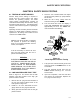
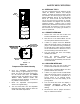
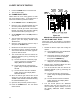
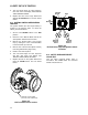
Table Of Contents
- Table of Contents
- Foreword
- CHAPTER 1 - SAFETY PRECAUTIONS
- CHAPTER 2 - INSTALLATION
- CHAPTER 3 - CONTROL PANEL OPERATING PROCEDURES
- CHAPTER 4 - INITIAL START-UP
- CHAPTER 5 - MODE OF OPERATION
- CHAPTER 6 - SAFETY DEVICE TESTING
- CHAPTER 7 - MAINTENANCE
- CHAPTER 8 - TROUBLESHOOTING GUIDE
- CHAPTER 9 - RS232 COMMUNICATION
- APPENDIX A - BOILER MENU ITEM DESCRIPTIONS
- APPENDIX B - STARTUP, STATUS AND FAULT MESSAGES
- APPENDIX C - TEMPERATURE SENSOR RESISTANCE CHART
- APPENDIX D - INDOOR/OUTDOOR RESET RATIO CHARTS
- APPENDIX E - BOILER DEFAULT SETTINGS
- APPENDIX F - ASSEMBLY DRAWINGS
- APPENDIX G - PIPING DIAGRAMS
- APPENDIX H - WIRING DIAGRAMS
- APPENDIX I - RECOMMENDED PERIODIC CHECK LIST
- APPENDIX J - CONTROL PANEL VIEWS
- APPENDIX K - RECOMMENDED SPARE PARTS
- STANDARD WARRANTY
SAFETY DEVICE TESTING
6-6
5. The unit should begin it’s start sequence,
then shut down and display PRG SWITCH
OPEN DURING PURGE.
1
7
2
1
7
1
1
6
9
1
7
0
6. Replace the wire on the Purge Switch and
depress the CLEAR button. The unit should
restart.
6.11 IGNITION SWITCH OPEN DURING
IGNITION
The Ignition Switch (and the Purge Switch) is
located on the Air/Fuel Valve. To check the
switch, proceed as follows:
1. Set the unit’s ON/OFF switch to the OFF
position.
2. Place the unit in Manual Mode and set the
valve position between 25% and 30%.
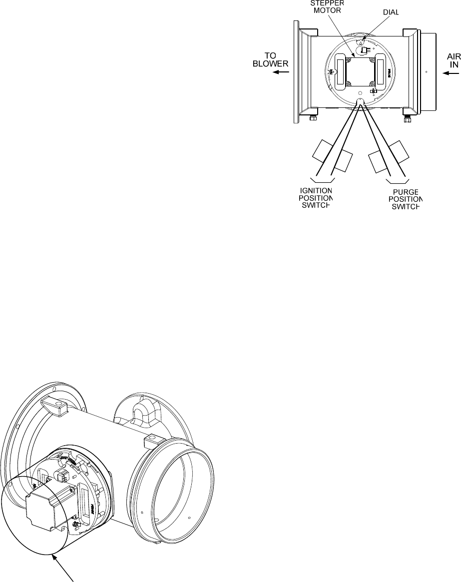
3. Remove the Air/Fuel Valve cover (Figure
6-5) by rotating the cover counterclockwise
to unlock and lift up to remove.
Figure 6-6
Air/Fuel Valve Purge and Ignition Switch
Locations
4. Remove one of the two wires (#169 or #170)
from the Ignition Switch (Figure 6-6).
5. Initiate a unit start sequence.
6. The unit should begin it’s start sequence
and then shut down and display IGN
SWITCH OPEN DURING IGNITION.
6.12 SAFETY PRESSURE RELIEF
VALVE TEST
Test the safety Pressure Relief Valve in
accordance with ASME Boiler and Pressure
Vessel Code, Section VI.
7. Replace the wire on the Ignition Switch and
press the CLEAR button. The unit should
restart.
AIR/FUEL VALVE COVER
(ROTATE CCW TO REMOVE)
Figure 6-5
Air/Fuel Valve Cover Location