
Manual
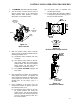
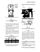
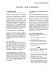
Table Of Contents
- Table of Contents
- Foreword
- CHAPTER 1 - SAFETY PRECAUTIONS
- CHAPTER 2 - INSTALLATION
- CHAPTER 3 - CONTROL PANEL OPERATING PROCEDURES
- CHAPTER 4 - INITIAL START-UP
- CHAPTER 5 - MODE OF OPERATION
- CHAPTER 6 - SAFETY DEVICE TESTING
- CHAPTER 7 - MAINTENANCE
- CHAPTER 8 - TROUBLESHOOTING GUIDE
- CHAPTER 9 - RS232 COMMUNICATION
- APPENDIX A - BOILER MENU ITEM DESCRIPTIONS
- APPENDIX B - STARTUP, STATUS AND FAULT MESSAGES
- APPENDIX C - TEMPERATURE SENSOR RESISTANCE CHART
- APPENDIX D - INDOOR/OUTDOOR RESET RATIO CHARTS
- APPENDIX E - BOILER DEFAULT SETTINGS
- APPENDIX F - ASSEMBLY DRAWINGS
- APPENDIX G - PIPING DIAGRAMS
- APPENDIX H - WIRING DIAGRAMS
- APPENDIX I - RECOMMENDED PERIODIC CHECK LIST
- APPENDIX J - CONTROL PANEL VIEWS
- APPENDIX K - RECOMMENDED SPARE PARTS
- STANDARD WARRANTY
INITIAL START-UP
4-6
4.5 OVER-TEMPERATURE LIMIT
SWITCHES
The unit contains both automatic and manual
reset over-temperature limit switches. These
switches are mounted on a plate next to the
VFD as shown in Figure 4-6. The switches can
be accessed by opening the front panel door of
the unit. The manual reset switch is not
adjustable and is permanently fixed at 210°F.
This switch will shut down and lock out the boiler
if the water temperature exceeds 210°F.
Following an over-temperature condition, it must
be manually reset by pressing the RESET
button before the boiler can be restarted. The
automatic reset over-temperature switch is
adjustable and allows the boiler to restart, once
the temperature drops below its temperature
setting. Set the automatic over-temperature
switch to the desired setting.
Figure 4-6
Over Temperature Limit Switch
Locations