Instruction No. GF-120 AERCO INTERNATIONAL, Inc., Northvale, New Jersey, 07647 USA Installation, Operation & Maintenance Instructions Benchmark 1.5LN Series Gas Fired Low NOx Boiler System Condensing, Modulating Forced Draft, Hot Water Boiler 1,500,000 BTU/H Input Applicable for Serial Numbers G-10-1002 and above Printed in U.S.A.
Telephone Support Direct to AERCO Technical Support (8 to 5 pm EST, Monday through Friday): 1-800-526-0288 The information contained in this installation, operation and maintenance manual is subject to change without notice from AERCO International, Inc. AERCO International, Inc. 159 Paris Avenue Northvale, NJ 07647-0128 www.aerco,com © AERCO International, Inc.
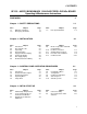
CONTENTS GF-120 - AERCO BENCHMARK 1.5LN GAS FIRED LOW NOx BOILER Operating & Maintenance Instructions FOREWORD A Chapter 1 – SAFETY PRECAUTIONS Para. 1-1 1-2 Subject Warnings & Cautions Emergency Shutdown Page 1-1 1-2 1-1 Para. 1-3 Subject Prolonged Shutdown Chapter 2 – INSTALLATION Para. 2.1 2.2 2.3 2.4 2.5 2.6 2.7 2.
CONTENTS Chapter 5 – MODE OF OPERATION Para. 5.1 5.2 5.3 5.4 5.5 Subject Introduction Indoor/Outdoor Reset Mode Constant Setpoint Mode Remote Setpoint Mode Direct Drive Modes Page 5-1 5-1 5-2 5-2 5-3 5-1 Para. 5.6 5.7 Subject Boiler Management System (BMS) Combination Control System (CCS) Page 5-4 5-5 Chapter 6 – SAFETY DEVICE TESTING PROCEDURES 6-1 Para. 6.1 6.2 6.3 6.4 6.5 6.6 6.
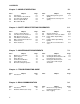
CONTENTS APPENDICES App A B C D Subject Boiler Menu Item Descriptions Startup, Status and Fault Messages Temperature Sensor Resistance Chart Indoor/Outdoor Reset Ratio Charts WARRANTIES Page A-1 B-1 C-1 App E F G H I D-1 J K Subject Boiler Default Settings Dimensional and Part Drawings Piping Drawings Wiring Schematics Recommended Periodic Testing Checklist Benchmark Control Panel Views Recommended Spare Parts Page E-1 F-1 G-1 H-1 I-1 J-1 K-1 W-1 iii
FOREWORD Foreword The AERCO Benchmark 1.5LN Boiler is a modulating unit. It represents a true industry advance that meets the needs of today's energy and environmental concerns. Designed for application in any closed loop hydronic system, the Benchmark's modulating capability relates energy input directly to fluctuating system loads. The Benchmark 1.
SAFETY PRECAUTIONS CHAPTER 1 SAFETY PRECAUTIONS 1.1 WARNINGS & CAUTIONS Installers and operating personnel MUST, at all times, observe all safety regulations. The following warnings and cautions are general and must be given the same attention as specific precautions included in these instructions. In addition to all the requirements included in this AERCO Instruction Manual, the installation of units MUST conform with local building codes, or, in the absence of local codes, ANSI Z223.
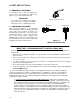
SAFETY PRECAUTIONS 1.2 EMERGENCY SHUTDOWN If overheating occurs or the gas supply fails to shut off, close the manual gas shutoff valve (Figure 1-1) located external to the unit. IMPORTANT MANUAL GAS SHUTOFF VALVE The Installer must identify and indicate the location of the emergency shutdown manual gas valve to operating personnel. 1.
SAFETY PRECAUTIONS Extracted Information From 248 CMR 5.08 (2) – Continued a. In the event that the side wall horizontally vented gas fueled equipment is installed in a crawl space or an attic, the hard wired carbon monoxide detector with alarm and battery back-up may be installed on the next adjacent floor level. b.
INSTALLATION CHAPTER 2 2.1 INTRODUCTION This Chapter provides the descriptions and procedures necessary to unpack, inspect and install the AERCO Benchmark 1.5 Boiler. Brief descriptions are also provided for each available mode of operation. Detailed procedures for implementing these modes are provided in Chapter 5.
INSTALLATION 44.5" 18" 24" 79" 30" 101" 24" 24" FRONT REAR 4" HIGH PAD Figure 2-1 Benchmark 1.5 Boiler Clearances WARNING KEEP THE UNIT AREA CLEAR AND FREE FROM ALL COMBUSTIBLE MATERIALS AND FLAMMABLE VAPORS OR LIQUIDS. CAUTION While packaged in the shipping container, the boiler must be moved by pallet jack or forklift from the FRONT ONLY.
INSTALLATION In multiple unit installations, it is important to plan the position of each unit in advance. Sufficient space for piping connections and future service/maintenance requirements must also be taken into consideration. All piping must include ample provisions for expansion. If installing a Combination Control Panel (CCP) system, it is important to identify the Combination Mode Boilers in advance and place them in the proper physical location.
INSTALLATION EXHAUST MANIFOLD A suitable piping compound, approved for use with natural gas, should be used. Any excess must be wiped off to prevent clogging of components. CONDENSATE TRAP UNION 3/4" NPT NIPPLE HOUSEKEEPING PAD 3/4" NPT NIPPLES TO FLOOR DRAIN SUPPORT 1" I.D. HOSE & CLAMP PARTIAL RIGHT SIDE VIEW Figure 2-5 Condensate Trap Installation 2.7 GAS SUPPLY PIPING The AERCO Benchmark 1.
INSTALLATION TERMINAL BLOCK NATURAL GAS SUPPLY 1-1/2” MANUAL GAS SHUTOFF VALVE GAS PRESSURE REGULATOR (REQUIRED FOR MASSACHUSETTS INSTALALTIONS ONLY) DIRT TRAP UPPER RIGHT CORNER OF FRONT PANEL Figure 2-7 AC Input Terminal Block Location 2.8.1 Electrical Power Requirements Figure 2-6 Manual Gas Shut-Off Valve Location 2.7.4 IRI Gas Train Kit The IRI gas train is an optional gas train configuration which is required in some areas for code compliance or for insurance purposes.
INSTALLATION 2.9 MODES OF OPERATION AND FIELD CONTROL WIRING TERMINAL STRIPS The Benchmark 1.5 Boiler is available in several different modes of operation. While each unit is factory configured and wired for its intended mode, some additional field wiring may be required to complete the installation. This wiring is typically connected to the Input/Output (I/O) Box located on the lower portion of the unit front panel (Figure 2-9) behind the removable front door.
INSTALLATION 2.9.1 Constant Setpoint Mode The Constant Setpoint Mode is used when it is desired to have a fixed setpoint that does not deviate. No wiring connections, other than AC electrical power connections, are required for this mode. However, if desired, fault monitoring or enable/disable interlock wiring can be utilized (see paragraphs 2.9.9.1 and 2.9.10). 2.9.2 Indoor/Outdoor Reset Mode This mode of operation increases supply water temperature as outdoor temperatures decrease.
INSTALLATION SENSOR IN and SENSOR COMMON terminals in the I/O Box (see Figures 2-9 and 2-10). Wire the sensor using a twisted shielded pair wire from 18 to 22 AWG. There is no polarity to observe when terminating these wires. The shield is to be connected only to the terminals labeled SHIELD in the I/O Box. The sensor end of the shield must be left free and ungrounded. When mounting the sensor, it must be located on the North side of the building where an average outside air temperature is expected.
INSTALLATION 2.10.9 EXHAUST SWITCH IN These terminals permit an external exhaust switch to be connected to the exhaust manifold of the boiler. The exhaust switch should be a normally open type switch (such as AERCO Part No. 123463) that closes (trips) at 500°F. 2.10.10 INTERLOCKS The unit offers two interlock circuits for interfacing with Energy Management Systems and auxiliary equipment such as pumps or louvers. These interlocks are called the Remote Interlock and Delayed Interlock (Figure 2-10).
INSTALLATION Selkirk Corporation Heatfab Division 130 Industrial Blvd. Turners Falls, MA 01376 Phone: 1-800-772-0739 www.heat-fab.com 2.13 COMBUSTION AIR The AERCO Benchmark Venting and Combustion Air Guide, GF-2050 MUST be consulted before any flue or combustion supply air venting is designed or implemented. Combustion air supply is a direct requirement of ANSI 223.1, NFPA-54, and local codes. These codes should be consulted before a permanent design is determined.
CONTROL PANEL OPERATING PROCEDURES CHAPTER 3 CONTROL PANEL OPERATING PROCEDURES 3.1 INTRODUCTION The information in this Chapter provides a guide to the operation of the Benchmark 1.5 Boiler using the Control Panel mounted on the front of the unit. It is imperative that the initial startup of this unit be performed by factory trained personnel. Operation prior to initial startup by factory trained personnel will void the equipment warranty.
CONTROL PANEL OPERATING PROCEDURES Table 3-1 Operating Controls, Indicators and Displays ITEM NO. 1 CONTROL, INDICATOR OR DISPLAY LED Status Indicators FUNCTION Four Status LEDs indicate the current operating status as follows: COMM Lights when RS-232 communication is occurring MANUAL Lights when the unit is being controlled using the front panel keypad.
CONTROL PANEL OPERATING PROCEDURES Table 3-1 Operating Controls, Indicators and Displays – Continued ITEM NO. 10 11 CONTROL, INDICATOR OR DISPLAY MENU Keypad FUNCTION Consists of 6 keys which provide the following functions for the Control Panel Menus: MENU Steps through the main menu categories shown in Figure 32. The Menu categories wrap around in the order shown. BACK Allows you to go back to the previous menu level without changing any information.
CONTROL PANEL OPERATING PROCEDURES 3.3 CONTROL PANEL MENUS The Control Panel incorporates an extensive menu structure which permits the operator to set up, and configure the unit. The menu structure consists of five major menu categories which are applicable to this manual. These categories are shown in Figure 3-2. Each of the menus shown, contain options which permit operating parameters to be viewed or changed. The menus are protected by a password levels to prevent unauthorized use.
CONTROL PANEL OPERATING PROCEDURES NOTE 3.5 SETUP MENU The following paragraphs provide brief descriptions of the options contained in each menu. Refer to Appendix A for detailed descriptions of each menu option. Refer to Appendix B for listings and descriptions of displayed startup, status and error messages. 3.4 OPERATING MENU The Operating Menu displays a number of key operating parameters for the unit as listed in Table 3-2.
CONTROL PANEL OPERATING PROCEDURES Table 3-3. Setup Menu Menu Item Display Passsword Available Choices or Limits Minimum Maximum 0 Language 9999 English 12:00 am 11:59 pm Date 01/01/00 12/31/99 Fahrenheit or Celsius Comm Address 0 Baud Rate 127 2400, 4800, 9600, 19.2K Software Ver 0.00 Fahrenheit 0 9600 Ver 9.99 3.
CONTROL PANEL OPERATING PROCEDURES Table 3-4. Configuration Menu - Continued Menu Item Display Remote Signal (If Mode = Remote Setpoint, Direct Drive or Combination) Available Choices or Limits Minimum Maximum 4 – 20 mA/1 – 5V 0 -20 mA/0 – 5V PWM Input (BMS) Network Default 4 – 20 mA, 1-5V Bldg Ref Temp (If Mode = Outdoor Reset) 40°F 230°F 70°F Reset Ratio (If Mode = Outdoor Reset) 0.1 9.9 1.
CONTROL PANEL OPERATING PROCEDURES 3.7 TUNING MENU The Tuning Menu items in Table 3-5 are Factory set for each individual unit. Do not change these menu entries unless specifically requested to do so by Factory-Trained personnel. 3.8 COMBUSTION CAL MENU The Combustion Cal Table 3-6 are used unit’s blower motor and air density at (Calibration) Menu items in to vary the speed of the based on air temperature prescribed Air/Fuel Valve positions (% open).
CONTROL PANEL OPERATING PROCEDURES 1. The DEMAND LED status indicator will light. 2. The unit checks to ensure that the Proof of Closure (POC) switch in the downstream Safety Shut-Off Valve (SSOV) is closed. See Figure 3-3 for SSOV location. (b) The igniter relay is activated and provides ignition spark. (c) The gas Safety Shut-Off Valve (SSOV) is energized (opened) allowing gas to flow into the Air/Fuel Valve. MANUAL SHUT-OFF VALVE TO AIR/FUEL VALVE SSOV GAS INLET Figure 3-3. SSOV Location Figure 3-4.
CONTROL PANEL OPERATING PROCEDURES 8. With the unit firing properly, it will be controlled by the temperature controller circuitry. The boiler’s VALVE POSITION will be continuously displayed on the front panel bargraph. Once the demand for heat has been satisfied, the Control Box will turn off the dual SSOV gas valves. The blower relay will be deactivated and the Air/Fuel Valve will be closed. Standby will be displayed. 3.
INITIAL START-UP CHAPTER 4 4.1 INITIAL START-UP REQUIREMENTS The requirements for the initial start-up of the Benchmark 1.5 Boiler consists of the following: • • • • • Complete installation Perform combustion calibration Set proper controls and limits Set up mode of operation (see Chapter 5) Test safety devices (see Chapter 6) Installation should be fully completed before performing initial start-up; and the start-up must be complete prior to putting the unit into service.
INITIAL START-UP 5. Attach one end of the plastic tubing to the barbed fitting and the other end to the 16 inch W.C. manometer. MANUAL SHUT-OFF VALVE HIGH GAS PRESSURE SWITCH TO AIR/FUEL VALVE LEAK DETECTION BALL VALVE GAS INLET SSOV 1/8" NPT PLUG (INSTALL MANOMETER HERE) LOW GAS PRESSURE SWITCH 4.2.3 Accessing the Vent Probe Port The unit contains NPT plug on the exhaust manifold at the rear of the unit as shown in Figure 4-2. Prepare the port for the combustion analyzer probe as follows: 1.
INITIAL START-UP BRASS HEX HEAD CAP (REMOVE TO ACCESS GAS PRESSURE ADJUSTMENT SCREW) 15. Once the oxygen level is within the specified range at 100%, lower the valve position to 80%. AIR/FUEL VALVE AIR INLET A A IRIS AIR DAMPER FRONT TYPICAL SSOV ACTUATOR WITH REGULATOR Figure 4-3 Gas Pressure Adjustment Screw Location 11. Increase the valve open position to 100% and verify that the gas pressure downstream of the SSOV remains at 3” W.C. Readjust pressure if necessary. 12.
INITIAL START-UP 19. Press the CHANGE key. SET Valve Position will begin to flash. 29. Press the down ▼ arrow key until CAL Voltage 60% is displayed. 20. Press the ▲ arrow key until the SET Valve Position reads 80%. Press the ENTER key. 30. Press the CHANGE key. CAL Voltage 60% will begin to flash. 21. Next, press the down (▼) arrow key until CAL Voltage 80% is displayed. 31. The oxygen level at the 60% valve position should be as shown below.
INITIAL START-UP 40. If the oxygen level is not within the specified range, adjust the level using the ▲ and ▼ arrow keys. This will adjust the output voltage to the blower motor as indicated on the display. Pressing the ▲ arrow key increases the oxygen level and pressing the ▼ arrow key decreases the oxygen level. 41. Once the oxygen level is within the specified range at 45%, press the ENTER key to store the selected blower output voltage for the 45% valve position. 42.
INITIAL START-UP 4.5 OVER-TEMPERATURE LIMIT SWITCHES The unit contains both automatic and manual reset over-temperature limit switches. These switches are mounted on a plate next to the VFD as shown in Figure 4-6. The switches can be accessed by opening the front panel door of the unit. The manual reset switch is not adjustable and is permanently fixed at 210°F. This switch will shut down and lock out the boiler if the water temperature exceeds 210°F.
MODE OF OPERATION CHAPTER 5 MODE OF OPERATION 5.1 INTRODUCTION The boiler is capable of being operated in any one of six different modes. The following paragraphs in this Chapter provide descriptions of each of these operating modes. Each boiler is shipped from the factory tested and configured for the ordered mode of operation. All temperature related parameters are at their factory default values which work well in most applications.
MODE OF OPERATION 7. Press the CHANGE key. The display will begin to flash. 8. Use the ▲ and ▼ arrow keys to select the desired Building Reference Temperature. 9. Press ENTER to save any changes. 10. Next, scroll through the Configuration Menu until the display shows Reset Ratio. 11. Press the CHANGE key. The display will begin to flash. 12. Use the ▲ and ▼ arrow keys to select the Reset Ratio determined in step 5. 13. Press ENTER to save the change. Refer to paragraph 3.
MODE OF OPERATION If the Network setting is selected for RS485 Modbus operation, a valid Comm Address must be entered in the Setup Menu. Refer to Modbus Communication Manual GF-114 for additional information. While it is possible to change the settings of temperature related functions, the unit is factory preset with settings that work well in most applications. It is suggested that an AERCO representative be contacted, prior to changing any temperature related function settings.
MODE OF OPERATION If the Network setting is selected for RS485 Modbus operation, a valid Comm Address must be entered in the Setup Menu. Refer to Modbus Communication Manual GF-114 for additional information. 5.5.1 Direct Drive Field Wiring The only wiring connections necessary for Direct Drive mode are connection of the remote signal leads from the source to the unit’s I/O Box. For either a 4-20mA/0-5V or a 0-20mA/0-5V setting, the connections are made at the ANALOG IN terminals in the I/O Box.
MODE OF OPERATION To change back to the BMS mode, simply press the AUTO/MAN switch. The REMOTE LED will again light and the MANUAL LED will go off. 5.7 COMBINATION CONTROL SYSTEM (CCS) NOTE Only BMS Model 168 can be utilized for the Combination Mode, not the BMS II (Model 5R5-384). A Combination Control System (CCS) is one that uses multiple boilers to cover both spaceheating and domestic hot water needs.
SAFETY DEVICE TESTING CHAPTER 6 SAFETY DEVICE TESTING 6.1 TESTING OF SAFETY DEVICES Periodic safety device testing is required to ensure that the control system and safety devices are operating properly. The boiler control system comprehensively monitors all combustion-related safety devices before, during and after the start sequence. The following tests check to ensure that the system is operating as designed. 4.
SAFETY DEVICE TESTING 6.3 HIGH GAS PRESSURE TEST To simulate a high gas pressure fault, refer to Figure 6-1 and proceed as follows: shut the unit off immediately and refer fault to qualified service personnel. 7. Close the drain and pressure relief valve used in draining the unit. 1. Remove the 1/8“ plug from the leak detection ball valve shown in Figure 6-1. 8. Open the water shut-off valve in the return piping to the unit. 2. Install a 0 – 16” W.C. manometer (or W.C.
SAFETY DEVICE TESTING 6.6 INTERLOCK TESTS The unit is equipped with two interlock circuits called the Remote Interlock and Delayed Interlock. Terminal connections for these circuits are located in the I/O Box (Figure 2-9) and are labeled REMOTE INTL’K IN and DELAYED INTL’K IN. These circuits can shut down the unit in the event that an interlock is opened. These interlocks are shipped from the factory jumpered (closed).
SAFETY DEVICE TESTING 6. Press the CLEAR button to reset the fault 7. The unit should start. 6.7 FLAME FAULT TESTS Flame faults can occur during ignition or while the unit is already running. To simulate each of these fault conditions, proceed as follows: 1. Set the ON/OFF switch to the OFF position. 2. Place the unit in the Manual Mode and set the valve position between 25% and 30%. 3.
SAFETY DEVICE TESTING 5. Re-enable the blower output drive voltage by performing the following steps: 6. The unit should fault and display SSOV SWITCH OPEN. (a) Press the MENU key until CONFIGURATION MENU is displayed. 7. Replace wire #148 and press the CLEAR button. (b) Press the ▲ arrow key until the ANALOG OUTPUT function is displayed, then press the CHANGE key. 8. Set the ON/OFF switch to ON to start the unit.
SAFETY DEVICE TESTING 5. The unit should begin it’s start sequence, then shut down and display PRG SWITCH OPEN DURING PURGE. 6. Replace the wire on the Purge Switch and depress the CLEAR button. The unit should restart. 6.11 IGNITION SWITCH OPEN DURING IGNITION 3. Remove the Air/Fuel Valve cover (Figure 6-5) by rotating the cover counterclockwise to unlock and lift up to remove. 4. Remove one of the two wires (#169 or #170) from the Ignition Switch (Figure 6-6). 170 2 17 2.
MAINTENANCE CHAPTER 7 MAINTENANCE 7.1 MAINTENANCE SCHEDULE The unit requires regular routine maintenance to keep up efficiency and reliability. For best operation and life of the unit, the following routine maintenance procedures should be performed in the time periods specified in Table 7-1. See Appendix I for a complete CSD-1 inspection check list.
MAINTENANCE 7.2 IGNITOR-INJECTOR The ignitor-injector (part no. 58023) is located on the burner plate at the top of the boiler. In addition to providing the ignition spark required to light the burner, the ignitor-injector also contains a gas injector tube which connects to the staged ignition assembly. Figure 7-1 shows the complete burner assembly removed from the boiler and indicates the location of the ignitorinjector flame detector and other related components. 4.
MAINTENANCE BLOWER GAS INJECTOR TUBE IGNITORINJECTOR 6. Thoroughly inspect the flame detector. If eroded, the detector should be replaced. Otherwise clean the detector with a fine emery cloth. 7. Reinstall the flame detector and flame detector gasket. 8. Reconnect the flame detector lead wire. 9. Reinstall the side and top panels on the unit. 12 0 BURNER PLATE Figure 7-3 7.
MAINTENANCE 13. Disconnect the flex hose from the air/fuel valve by loosening the hose clamp. 14. Remove the four (4) 5/16-18 hex head screws securing the blower to the burner plate (Figure 7-5). 15. Remove the blower and air/fuel valve from the burner plate by lifting straight up. Also, remove the blower gasket. 16. Remove the eight (8) 3/8-16 nuts from the burner flange (Figure 7-4) using a 9/16” wrench. NOTE The burner assembly is heavy, weighing approximately 25 pounds.
MAINTENANCE gasket and float in the condensate trap and replace the trap cover. 8. Reassemble all piping and hose connections to the condensate trap inlet and outlet. Reconnect trap to exhaust manifold drain. COVER THUMB SCREWS (4) O-RING GASKET FLOAT ORIFICE GASKET INLET 3/4 NPT PORT 3/4 NPT PORT OUTLET Figure 7-5 External Condensate Trap Figure 7-4 Burner Assembly Exploded View 7.7 CONDENSATE DRAIN TRAP The Benchmark 1.5 Boiler contains a condensate trap as shown in Chapter 2, Figure 2-5.
TROUBLESHOOTING Chapter 8- TROUBLESHOOTING GUIDE 8.1 INTRODUCTION This troubleshooting guide is intended to aid service/maintenance personnel in isolating the cause of a fault in a Benchmark 1.5 Boiler. The troubleshooting procedures contained herein are presented in tabular form on the following pages. These tables are comprised of three columns labeled: Fault Indication, Probable Cause and Corrective Action. The numbered items in the Probable Cause and Corrective Action columns correspond to each other.
TROUBLESHOOTING TABLE 8-1. BOILER TROUBLESHOOTING FAULT INDICATION AIRFLOW FAULT DURING IGNITION PROBABLE CAUSES 1. Blower stopped running due to thermal or current overload 2. Blocked Blower inlet or inlet ductwork 3. Blocked Blower proof switch 4. Blocked blocked-air inlet switch 5. Defective Blower proof switch 6. Defective blocked-air inlet switch 7. Loose temperature to AUX connection in I/O Box 8. Defective temperature sensor 9.
TROUBLESHOOTING TABLE 8-1. BOILER TROUBLESHOOTING – Continued FAULT INDICATION PROBABLE CAUSES CORRECTIVE ACTION AIRFLOW FAULT DURING PURGE 1. Blower not running or running too slow 1. Start the unit. If the blower does not run check the blower solid state relay for input and output voltage. If the relay is okay, check the blower. 2. Start the unit. If the blower runs, check the airflow switch for continuity. Replace the switch if there is no continuity. 3.
TROUBLESHOOTING TABLE 8-1. BOILER TROUBLESHOOTING – Continued FAULT INDICATION PROBABLE CAUSES CORRECTIVE ACTION DELAYED INTERLOCK OPEN 1. Delayed Interlock Jumper not installed or removed. 2. Device proving switch hooked to interlocks is not closed 1. Check for a jumper properly installed across the delayed interlock terminals in the I/O box. 2. If there are 2 external wires on these terminals, check to see if an end switch for a device such as a pump, louver, etc. is tied these interlocks.
TROUBLESHOOTING TABLE 8-1. BOILER TROUBLESHOOTING – Continued FAULT INDICATION (continued) PROBABLE CAUSES 7. Carbon or other debris on Burner. 8. Staged ignition ball valve closed. 9. Staged ignition solenoid valve doesn’t open. 10. Clogged staged ignition piece. FLAME LOSS DURING RUN 1. Worn Flame Detector or cracked ceramic. 2. Defective Regulator. 3. Poor combustion calibration. 4. Debris on burner. HEAT DEMAND FAILURE HIGH EXHAUST TEMPERATURE 5. Blocked condensate drain. 1.
TROUBLESHOOTING TABLE 8-1. BOILER TROUBLESHOOTING – Continued FAULT INDICATION HIGH GAS PRESSURE PROBABLE CAUSES 1. Incorrect supply gas pressure. 2. Defective SSOV Actuator. 3. Defective High Gas Pressure Switch 4. Gas pressure snubber not installed. HIGH WATER TEMP SWITCH OPEN 1. Faulty Water temperature switch. 2. Incorrect PID settings. 3. Faulty shell temperature sensor. 4. Unit in Manual mode 5. Unit setpoint is greater than Over Temperature Switch setpoint. 6.
TROUBLESHOOTING TABLE 8-1. BOILER TROUBLESHOOTING – Continued FAULT INDICATION IGN BOARD COMM FAULT IGN SWTCH CLOSED DURING PURGE PROBABLE CAUSES 1. Communication fault has occurred between the PMC board and Ignition/Stepper (IGST) board 1. Air/Fuel Valve not rotating 2. Defective or shorted switch 3. Switch wired incorrectly 4. Defective Power Supply Board or fuse 5. Defective IGST Board IGN SWTCH OPEN DURING IGNITION 1. Air/Fuel Valve not rotating to ignition position. 2.
TROUBLESHOOTING TABLE 8-1. BOILER TROUBLESHOOTING – Continued FAULT INDICATION INTERLOCK OPEN LINE VOLTAGE OUT OF PHASE LOW GAS PRESSURE PROBABLE CAUSES 1. Interlock jumper not installed or removed 2. Energy Management System does not have boiler enabled. 3. Device proving switch hooked to interlocks is not closed. 1. Line and Neutral switched in AC Power Box. 2. Incorrect power supply transformer wiring. 1. Incorrect supply gas pressure. 2. Defective Low Pressure Gas Switch LOW WATER LEVEL 1.
TROUBLESHOOTING TABLE 8-1. BOILER TROUBLESHOOTING – Continued FAULT INDICATION (continued) PROBABLE CAUSES 2. Defective or shorted switch. 3. Switch wired incorrectly. 4. Defective Power Supply Board or fuse 5. Defective IGST Board PRG SWTCH OPEN DURING PURGE 1. Defective purge switch. 2. No voltage present at switch. 3. Switch wired incorrectly. 4. Defective Power Supply Board or fuse 5. Defective IGST Board OUTDOOR TEMP SENSOR FAULT REMOTE SETPT SIGNAL FAULT 8-9 1. Loose or broken wiring. 2.
TROUBLESHOOTING TABLE 8-1. BOILER TROUBLESHOOTING – Continued FAULT INDICATION RESIDUAL FLAME SSOV FAULT DURING PURGE SSOV FAULT DURING RUN SSOV RELAY FAILURE PROBABLE CAUSES 1. SSOV not fully closed. 2. Defective Flame Detector See SSOV SWITCH OPEN 1. SSOV relay failed on board. 1. Press CLEAR button and restart unit. If fault persists, replace Ignition/Stepper (IGST) Board. 2. The Neutral and Earth Ground are not connected at the source and therefore there is a voltage measured between the two.
TROUBLESHOOTING TABLE 8-1. BOILER TROUBLESHOOTING – Continued 8.2 FAULT INDICATION PROBABLE CAUSES CORRECTIVE ACTION (continued) 2. Air/Fuel Valve unplugged. 3. Loose wiring connection to the stepper motor. 4. Defective Air/Fuel Valve stepper motor. 5. Defective Power Supply Board or fuse 6. Defective IGST Board 2. Check that the Air/Fuel Valve is connected to the Control Box. 3. .Inspect for loose connections between the Air/Fuel Valve motor and the wiring harness. 4. Replace stepper motor. 5.
TROUBLESHOOTING MANUAL SHUT-OFF VALVE HIGH GAS PRESSURE SWITCH TO AIR/FUEL VALVE LEAK DETECTION BALL VALVE GAS INLET SSOV 1/8" NPT PLUG (INSTALL MANOMETER HERE) LOW GAS PRESSURE SWITCH Figure 8-2 Staged Ignition Solenoid Location STAGED IGNITION BALL VALVE Figure 8-1 High Pressure Gas Switch & Snubber Locations Figure 8-3 Damping Orifice Location 8-12
RS232 COMMUNICATION CHAPTER 9 RS232 COMMUNICATION 9.1 INTRODUCTION The RS232 port on the front panel of the C-More Control Box (Figure 3-1) can be interfaced to a laptop computer or other suitable terminal using a RS232 adapter cable. RS232 communication can be accomplished using any “Dumb Terminal” emulation, such as “Hyper Terminal” which is included with Microsoft Windows.
RS232 COMMUNICATION (c) Menu changes will be stored in nonvolatile memory. 9. To redisplay the menu and view the option which was just changed in step 5, enter D and press . 10. To display the Fault (F) Log, Sensor (S) Log or Time (T) Line Log, press F, S or T followed by . Refer to paragraph 9.4 for descriptions and samples of these data logs. 11. To log off and terminate the RS232 communication link, press L followed by . 9.
RS232 COMMUNICATION Table 9-1. Sample Fault Log Display No. 0 1 2 Fault Message Direct Drive Signal Fault Low Gas Pressure Loss of Power Cycle 609 366 0 Date 1/10/02 7/04/01 1/01/01 Time 8:42am 5:29pm 11:50am Table 9-2.
APPENDIX A APPENDIX A - BOILER MENU ITEM DESCRIPTIONS MENU LEVEL & OPTION DESCRIPTION OPERATING MENU Active Setpoint This is the setpoint temperature to which the control is set when operating in the Constant Setpoint, Remote Setpoint or Outdoor Reset Mode. When in the Constant Setpoint Mode, this value is equal to the Internal Setpoint setting in the Configuration Menu. When in the Remote Setpoint Mode, this value is the setpoint equivalent to the remote analog signal supplied to the unit.
APPENDIX A APPENDIX A - BOILER MENU ITEM DESCRIPTIONS - CONTINUED MENU LEVEL & OPTION DESCRIPTION SETUP MENU Password Allows password to be entered. Once the valid password (159) is entered, options in the Setup, Configuration and Tuning Menus can be modified. Language Permits selection of English, Spanish or French for displayed messages. Default is English. Time Displays time from 12:00 am to 11:59 pm.
APPENDIX A APPENDIX A - BOILER MENU ITEM DESCRIPTIONS - Continued MENU LEVEL & OPTION DESCRIPTION CONFIGURATION MENU (Cont.) Reset Ratio Permits setting of Reset Ratio when operating boiler in the Outdoor Reset Mode. Reset Ratio is adjustable from 0.1 to 9.9. Default is 1.2. Outdoor Sensor Allows outdoor sensor function to be enabled or disabled. Default is disabled. System Start Tmp If outdoor sensor is enabled, this menu item allows the system start temperature to be set from 30 to 100°F.
APPENDIX A APPENDIX A - BOILER MENU ITEM DESCRIPTIONS - Continued MENU LEVEL & OPTION DESCRIPTION CONFIGURATION MENU (Cont.) HI DB Setpt EN Operating at a Valve Position below this value will inhibit the DEADBAND feature. When operating at a Valve Position below this value, the effective Setpoint is equal to Active Setpoint + DEADBAND HIGH. Setting range is from 0 to 100. (Default is 30) Demand Offset This entry will reduce excessive ON/OFF cycling in AUTO mode.
APPENDIX A MENU LEVEL & OPTION DESCRIPTION TUNING MENU Prop Band Generates a fire rate based on the error that exists between the setpoint temperature and the actual outlet temperature. If the actual error is less than the proportional band setting (1 to 120°F), the fire rate will be less than 100%. If the error is equal to or greater than the proportional band setting, the fire rate will be 100%.
APPENDIX B APPENDIX B - STARTUP, STATUS AND FAULT MESSAGES TABLE B-1. STARTUP AND STATUS MESSAGES MESSAGE DISABLED HH:MM pm MM/DD/YY STANDBY DEMAND DELAY XX sec PURGING XX sec IGNITION TRIAL XX sec FLAME PROVEN WARMUP XX sec WAIT DESCRIPTION Displayed if ON/OFF switch is set to OFF. The display also shows the time and date that the unit was disabled. Displayed when ON/OFF switch is in the ON position, but there is no demand for heat. The time and date are also displayed.
APPENDIX B TABLE B-2.
APPENDIX B TABLE B-2. FAULT MESSAGES - Continued FAULT MESSAGE RESIDUAL FLAME HEAT DEMAND FAILURE IGN BOARD COMM FAULT DIRECT DRIVE SIGNAL FAULT REMOTE SETPT SIGNAL FAULT OUTDOOR TEMP SENSOR FAULT OUTLET TEMP SENSOR FAULT FFWD TEMP SENSOR FAULT HIGH WATER TEMPERATURE LINE VOLTAGE OUT OF PHASE STEPPER MOTOR FAILURE NETWORK COMM FAULT FAULT DESCRIPTION The Flame signal was seen for more than 60 seconds during standby. The Heat Demand Relays on the Ignition board failed to activate when commanded.
APPENDIX C TEMPERATURE SENSOR RESISTANCE VOLTAGE CHART (BALCO) TEMP (°F) -40 -30 -20 -10 0 10 20 30 40 50 60 70 80 90 100 110 120 130 140 150 160 170 180 190 200 210 220 230 240 250 RES (OHMS) 779.0 797.5 816.3 835.4 854.8 874.6 894.7 915.1 935.9 956.9 978.3 1000.0 1022.0 1044.4 1067.0 1090.0 1113.3 1137.0 1160.9 1185.2 1209.5 1234.7 1260.0 1285.6 1311.4 1337.7 1364.2 1391.0 1418.2 1445.7 VOLTS* 1.93 1.96 1.99 2.02 2.05 2.07 2.10 2.12 2.15 2.17 2.20 2.23 2.25 2.27 2.30 2.32 2.34 2.36 2.39 2.41 2.43 2.
APPENDIX D APPENDIX D. - INDOOR/OUTDOOR RESET RATIO CHARTS Table D-1. Header Temperature for a Building Reference Temperature of 50F RESET RATIO Air Temp 0.6 0.8 1.0 1.2 1.4 1.6 1.8 2.0 2.2 2.
APPENDIX D Table D-3. Header Temperature for a Building Reference Temperature of 65F RESET RATIO Air Temp 0.6 0.8 1.0 1.2 1.4 1.6 1.8 2.0 2.2 2.
APPENDIX D Table D-5. Header Temperature for a Building Reference Temperature of 75F RESET RATIO Air Temp 0.6 0.8 1.0 1.2 1.4 1.6 1.8 2.0 2.2 2.
APPENDIX D Table D-7. Header Temperature for a Building Reference Temperature of 90F RESET RATIO Air Temp 0.6 0.8 1.0 1.2 1.4 1.6 1.8 2.0 2.2 2.
APPENDIX E BOILER DEFAULT SETTINGS MENU & OPTION FACTORY DEFAULT Setup Menu Password 0 Language English Unit of Temp Comm Address Baud Rate Fahrenheit 0 9600 Configuration Menu Internal Setpt 130°F Unit Type BMK Boiler LN Unit Size 1.5 MBTU Boiler Mode Constant Setpoint Remote Signal (If Mode = Remote Setpoint, Direct Drive or Combination) 4 – 20 mA / 1-5V Bldg Ref Temp (If Boiler Mode = Outdoor Reset) 70°F Reset Ratio (If Boiler Mode = Outdoor Reset) 1.
APPENDIX E BOILER DEFAULT SETTINGS - Continued MENU & OPTION FACTORY DEFAULT Configuration Menu --Continued Network Timeout 30 seconds Hi DB Setpt En 30 Demand Offset 10 Deadband High 2 Deadband Low 2 Tuning Menu Prop Band 70°F Integral Gain 1.00 Derivative Time E-2 0.
210 160 240 TEST PRESS. (PSIG) 24-9/16 (62.4) 6" EXHAUST OUTLET 1-1/2" NPT DRAIN CONN. 5-15/16 (15.1) 3 (7.6) 51-7/8 (131.8) 8-1/8 (20.6) 4" CONCRETE PAD - SET UNIT FLUSH AT REAR 55-1/2 (141.0) 3/4" NPT GAS VENT CONN. FOR "IRI" GAS TRAIN OPTION" ONLY 1-1/2" NPT NATURAL GAS INLET CONN. 3"-150# FLG'D COLD WATER INLET CONN. 4-1/16 (12.2) 4-13/16 (12.2) PRESS./TEMP. GAUGE PRESS. RELIEF VALVE 1500 MIN. RELIEF VA. CAPACITY MBH 1) ALL DIMENSIONS SHOWN ARE IN INCHES (CENTIMETERS).
NOTES: F-2 1) ALL HOLES ARE FLUSH WITH THE BOTTOM SURFACE OF THE FRAME 2) ALL DIMENSIONS SHOWN ARE IN INCHES (CENTIMETERS) FRONT INTERNATIONAL, INC. NORTHVALE, NJ 07647 *NOT TO SCALE* DRWN BY:SJD DATE:10/12/07 SD - A - 730 A REV BENCHMARK 1.
APPENDIX F F-3
F-4 79" 18" 1) THIS APPLIANCE MAY BE INSTALLED ON COMBUSTIBLE FLOORING 2) MINIMUM CLEARANCES TO ADJACENT CONSTRUCTION ARE AS FOLLOWS: LEFT & RIGHT SIDES: 24" FRONT: 24" REAR: 42" * CEILING HIEGHT: 101" INSTALLATION CLEARANCES: 44.5" SIDE VIEW 101" 24" FRONT 24" INTERNATIONAL, INC. NORTHVALE, NJ 07647 *NOT TO SCALE* DRWN BY:SJD DATE:10/12/07 SD - A - 731 A REV BENCHMARK 1.
APPENDIX F F-5
F-6 1.5" DOUBLE BODY SSOV CONNECTING FLANGE P/N: 124178 SAFETY SHUT OFF VALVE ACTUATOR WITHOUT PROOF OF CLOSURE SWITCH P/N: 69038 NORMALLY OPEN VENT VALVE P/N: 122774 3/4" SCH.40 PIPE 1.5" SCH.40 PIPE ENTIRE BMK 1.5 LN IRI GAS TRAIN P/N: 22039-2 1.5" DOUBLE BODY SSOV P/N: 124137 SAFETY SHUT-OFF VALVE ACTUATOR P/N: 64048 HIGH GAS PRESSURE SWITCH P/N: 61002-3 *NOT TO SCALE* DRWN BY:SJD DATE:10/11/07 AP - A - 830 B REV BENCHMARK 1.
APPENDIX F F-7
APPENDIX F HOSES,GASKETS, & INSULATION EXHAUST MANIFOLD ITEM PART NO. QTY ITEM PART NO. DESCRIPTION 1 43045 1 EXHAUST MANIFOLD 2 3 84020 1 EXHAUST MANIFOLD SEAL QTY 22 88003 1 24 88004 1 25 62005 1 DESCRIPTION O-RING #2-339 (A/F VALVE) O-RING #2-244 BUNA - N (BLOWER) CORD GRIP GAS TRAIN ASSEMBLY ITEM PART NO.
APPENDIX F OTHER DUAL FUEL COMPONENTS CONTROLS ITEM PART NO. QTY DESCRIPTION ITEM PART NO. QTY DESCRIPTION "PROPANE" LABEL 26 65090 1 27 123966 1 DRIVE REACTOR OVER TEMP SWITCH AUTO 28 123552 1 OVER TEMP SWITCH MANUAL 29 61002-5 1 BLOCKED INLET SWITCH (1)(4)(5) 58 63032 1 30 60011-1 1 BLOWER PROOF SWITCH (4) 59 65024 1 31 161560 1 (1)(4) 60 33036 1 (4) 61 72030 1 (1)(4) 62 63034 1 I /O WIRING BOX (1)(4) 56 72031 1 (1)(4) 57 72032 1 "NAT.
APPENDIX F F-10 F-10
APPENDIX F APPENDIX F 16 25 46 44 B 47 24 21 22 5 6 29 30 54 8 48 AERCO DETAIL B INTERNATIONAL, INC. NORTHVALE, NJ 07647 BENCHMARK 1.
APPENDIX F 27 26 28 42 32 C 31 34 DETAIL C 48 74 47 61 AERCO 59 INTERNATIONAL, INC. NORTHVALE, NJ 07647 BENCHMARK 1.
APPENDIX F 66 67 68 64 65 AERCO INTERNATIONAL, INC. NORTHVALE, NJ 07647 BENCHMARK 1.
APPENDIX F 71 73 69 72 70 AERCO INTERNATIONAL, INC. NORTHVALE, NJ 07647 BENCHMARK 1.
APPENDIX G G-1
G-2 NOTES: DRIP TRAP GAS SUPPLY SYSTEM PUMP AUTOMATIC AIR VENT P&T AIR SEPARATOR * CONDENSATE DRAIN TRAP 1-1/2" NPT DRAIN CONN. DIAPHRAGM TYPE EXPANSION TANK CHECK VALVE (TYP.) RELIEF VALVE (TYP.) P&T 7) A GAS REGULATOR IS MANDATORY FOR THE STATE OF MASSACHUSETTS, REGARDLESS OF SUPPLY PRESSURE. SEE DIAGRAM 1 6) WHEN AVAILABLE GAS PRESSURE IS GREATER THAN 2.0 PSIG, A LOCK-UP STYLE REGULATOR MUST BE INSTALLED DOWNSTREAM OF THE 2" MANUAL SHUTOFF VALVE TO BRING THE GAS PRESSURE DOWN TO 2.0 PSIG.
APPENDIX G G-3
APPENDIX G G-4
APPENDIX G G-5
APPENDIX H H-1
APPENDIX H H-2
APPENDIX H H-3
APPENDIX H CONTROL BOX CONNECTORS 16-PIN CONNECTOR 24-PIN CONNECTOR 1 231 2 3 232 4 5 234 233 6 7 236 235 9 10 11 12 8 237 238 240 239 241 13 14 15 16 17 18 19 20 21 22 23 24 242 244 243 245 246 250 247 251 252 253 16 254 226 J3 1 2 3 4 5 6 7 8 9 10 11 12 13 14 15 1 2 3 4 5 6 7 220 221 8 219 7 6 216 5 4 215 3 2 213 214 1 212 211 J2 8 1 2 3 4 5 6 7 8 9 10 11 12 1 OUT 2 IN REMOTE INTLK 3 IN EXHAUST TEMP OUT 5 4 DEL
APPENDIX I RECOMMENDED PERIODIC TESTING CHECK LIST WARNING NOTE: Periodic testing of all boiler controls and safety devices is required to determine that they are operating as designed. Precautions shall be taken while tests are being performed to protect against bodily injury and property damage. The owner or user of an automatic boiler system should set up a formal system of periodic preventive maintenance and testing. Tests should be conducted on a regular basis and the results recorded in a log-book.
APPENDIX J BENCHMARK CONTROL PANEL EXPLODED VIEW J-1
P1 P2 P3 P4 P5 P6 APPENDIX J BENCHMARK CONTROL PANEL REAR VIEW J-2
APPENDIX K RECOMMENDED SPARE PARTS LISTS NOTE Refer to the Parts List Illustrations in Appendix F for the locations of the recommended and optional spare parts listed in the following Tables. Table K-1.
STANDARD WARRANTY: Benchmark Gas-Fired Hydronic Boiler INTERNATIONAL, INC. PRESSURE VESSEL/HEAT EXCHANGER: 7 YEARS FROM SHIPMENT The pressure vessel/heat exchanger shall carry a (7) seven year non-prorated warranty from shipment against any failure due to condensate corrosion, thermal stress, mechanical defects or workmanship. Operation of the boiler using contaminated air will void the warranty.
STANDARD WARRANTY: Benchmark Gas-Fired Hydronic Boiler INTERNATIONAL, INC. AERCO shall accept no responsibility if such item has been improperly installed, operated, or maintained or if the buyer has permitted any unauthorized modification, adjustment, and/or repairs to the item. The use of replacement parts not manufactured or sold by AERCO will void any warranty, express or limited. In order to process a warranty claim a formal purchase order number is required prior to shipment of any warranty item.