
Owner manual

CHAPTER 3: CONTROL PANEL OPERATION
Page 38 of 152 PR2: 05/09/12
Benchmark 1.5LN Low NOx Boiler
Operation and Maintenance Manual
OMM-0041_0D
GF-120
AERCO International, Inc. • 100 Oritani Dr. • Blauvelt, NY 10913 • Ph: 800-526-0288
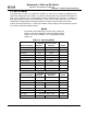
Table 3-6: Combustion Cal Menu
Available Choices or Limits
Menu Item Display
Minimum
Maximum
Default
CAL Voltage 16% .25 8.20 1.80v
CAL Voltage 30% .25 8.20 3.20v
CAL Voltage 45% .25 8.20 3.70v
CAL Voltage 60% .25 8.20 3.80
CAL Voltage 80% .25 8.20 4.60
CAL Voltage 100% .25 8.20 6.00
SET Valve Position 0% 100% 0%
Blower Output Monitor Blower Output Voltage .00
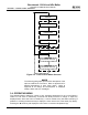
2.9 START SEQUENCE
When the Control Box ON/OFF switch is set to the ON position, it checks all pre-purge safety
switches to ensure they are closed. These switches include:
• Safety Shut-Off Valve Proof of Closure (POC) switch
• Low Water Level switch
• High Water Temperature switch
• High Gas Pressure switch
• Low Gas Pressure switch
• Blower Proof switch
• Blocked Inlet switch
If all of the above switches are closed, the READY light above the ON/OFF switch will light and
the unit will be in the Standby mode.
When there is a demand for heat, the following events will occur:
NOTE
If any of the Pre-Purge safety device switches are open,
the appropriate fault message will be displayed. Also, the
appropriate fault messages will be displayed throughout
the start sequence, if the required conditions are not
observed.
1. The DEMAND LED status indicator will light.
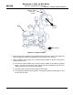
2. The unit checks to ensure that the Proof of Closure (POC) switch in the downstream Safety
Shut-Off Valve (SSOV) is closed. See Figure 3-3 for SSOV location.
3. With all required safety device switches closed, a purge cycle will be initiated and the
following events will occur:
a) The Blower relay energizes and turns on blower.
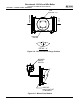
b) The Air/Fuel Valve rotates to the full-open purge position and closes purge position
switch. The dial on the Air/Fuel Valve (Figure 3-4) will read 100 to indicate that it is full-
open (100%).
c) The VALVE POSITION bargraph will show 100%.