
Manual


800-543-9038 USA 866-805-7089 CANADA 203-791-8396 LATIN AMERICA
8
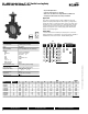
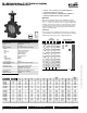
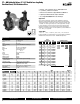
F7…HD Butterfl y Valves 2”–24” Ductile Iron Lu
g
Body
Resilient Seat
,
304 Stainless Dis
c
Technical Data
S
ervic
e
chilled, hot water, 60% gl
y
col
Fl
ow c
h
aracter
is
t
ic
modifi ed linea
r
A
c
ti
o
n
90
° r
o
t
a
ti
on
S
ize
s
2”
to
24”
Type of end fi ttin
g
for use with AN
S
I 125/150 fl anges
Material
s:
B
od
y
Body fi nis
h
Disc
S
eat
S
haf
t
O-rin
g
Upper bushin
g
Middl
e
b
us
hi
ngs
L
ower
b
us
hi
ng
ductile iron A
S
TM A536
epoxy pow
d
er coate
d
304
s
ta
i
n
l
e
ss
s
tee
l
EPDM
s
tan
d
ar
d
416
s
tainle
ss
s
tee
l
E
PDM
RPTFE
RPTFE
RPTFE
Media temperature ran
g
e -22°F to 250°F [-30°C to 120°C]
O
peration ambien
t
temperature ran
ge
-22°F to 122°F [-30°C to 50°C]
B
ody pressure ratin
g
AS
ME/AN
S
I
C
lass 125/150
(
200 psi at -30°F to 275°F
)
C
lose-off
p
ressur
e
200
ps
i
(2”
-
12”)
,
1
5
0
ps
i
(14”
-
24”)
R
angea
bili
t
y
1
0:1 (
f
or 30° to 70° range)
Maximum Velocit
y
1
2 FP
S
• 200 psi (2” to 12”) and 150 psi (14”-30”) bubble tight shut-of
f
• Lon
g
stem desi
g
n allows for 2” insulation
• Valve face-to-face dimensions compl
y
with API 609 & MSS-SP-67
• Completel
y
assembled and tested, read
y
for installation
• Tees compl
y
with A
S
ME/AN
S
I B16.1
C
lass 125 fl ange
s
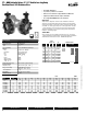
Applicatio
n
These valves are designed to meet the needs of HVAC and commercial
a
pplications requiring bubble tight shut off for liquids. T
y
pical applications
i
nclude chiller isolation, cooling tower isolation, change-over systems, large
a
ir handler coil control, bypass and process control applications. The large
C
v
values provide for an economical control valve solution for larger fl ow
a
pplications. Designed for use in Victaulic piping systems when mated to
V
ictaulic 41 series fl ange nipples. Fail safe operation is possible with NSV-SY
s
er
i
es
b
attery
b
ac
k
up systems
.
Jobsite Not
e
V
a
l
ves s
h
ou
ld
b
e store
d
i
n a weat
h
er
p
rotecte
d
area
p
r
i
or to construct
i
on.
C
omplete installation recommendations can be found in Belimo’s Installation
a
nd Maintenance Instructions for F6/F7…HD/HDU Butterfl y Valves.
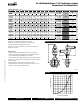
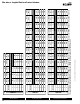
V
a
l
ve
Nominal
S
ize
T
ype
S
uitable Actuator
s
C
v
90°
C
v
60°
IN
DN
[mm]
2-way
Spring
Non-Spring
11
5
44
2”
5
0
F
75
0HD
AF Series
AM
GM Series
SY Series
196
7
5
2½”
6
5
F
7
6
5
HD
3
02 116
3
”
80
F780HD
6
00
2
30
4
” 100 F7100HD
10
22
39
2
5
”12
5
F712
5
HD
1
579 605
6
” 150 F7150HD
3136 1202
8
” 200 F7200HD
53
4
0
20
47
10
” 2
50
F72
50
HD
8
2
50
306
2
1
2”
300
F7
300
HD
1191
7
4568
14”
350
F
7
350HD
1
6388 6282
1
6” 400 F7400HD
2
1705 8320
1
8” 450 F7450HD
2
7908
1
0698
2
0” 500 F7500HD
43116
16
5
28
24”
600
F
7
600HD
M
O
D
O
N
/
OFF
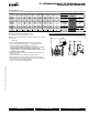
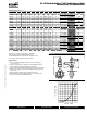
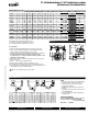
Valve Size
C
v
1
0
°
20
°
30
°
40
°
50°
60
°
70
°
80°
90
°
F
75
0HD
2”
11
5 .
06
3
7
15
27
44
7
0
105
11
5
F
7
6
5
HD
2½”
196
.
10
6
12
25
45
75
119
1
7
8
196
F
7
80HD
3”
302
.
20
9
18
39
7
0
116
183
2
7
5
302
F
7
100HD
4”
600
.
30
17
36
78
139
230
364
5
46
600
F712
5
HD
5”
1
0
22 .
50
2
9
61
133
2
37
39
2
6
2
0
930
1
0
22
F
7
1
5
0HD
6”
1
57
9
.
80
4
5
95
20
5
366
60
5
9
5
8
1437
1
57
9
F
7
200HD
8”
3136
2
89
188
408
7
27
1202
1903
28
5
4
3136
F72
50
HD
10”
53
4
0
3
1
5
1
3
2
0
69
412
37
2
0
47
3
24
0
4
859
53
4
0
F7300HD
1
2
”
8250
4
234
4
95
1
072 191
1
3062 5005 750
7
8250
F7350HD
1
4
”
11917
6
338 715
1
549 276
1
4568 7230 1084
4
11917
F7400HD
1
6
”
16388
8
464
9
83
2
130 379
7
6282 9942 14913 16388
F74
50
HD
18”
217
05
11
6
1
5
1
30
2
28
22
50
2
8
83
2
0
1
3
1
68
1
9
7
5
2
2
17
05
F7500HD 20
”
27908 14 791 1674
3
628 6465 10698 16931 25396
2
7908
F7600HD 24
”
4
3116 22 1222 2587 5605 9989 16528 26157 39236 43116
0
7/10 - Subject to change. © Belimo Aircontrols (USA), Inc.