
Manual

800-543-9038 USA 866-805-7089 CANADA 203-791-8396 LATIN AMERICA
4
0
0
7/10 - Subject to change. © Belimo Aircontrols (USA), Inc.
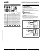
FLANGE BOLTING RECOMMENDATION
S
Lug Valves, 2”-30”, ANSI 125/150 Bolt Pattern
V
alve
S
ize
T
hread
S
ize
N
um
b
er
R
equ
i
re
d
B
olt Length
S
emi-Lug Butterfl
y
(i
nc
h
es
)
2
”
5
/
8-11
4
1
.2
5
2
-
1/2”
5
/8
-
11
4
1
.5
0
3
”
5
/
8-11
4
1
.50
4”
5
/8
-
11
8
1
.75
5
”
3/4
-
10
8
1
.75
6”
3/4
-
10
8
2
.
00
8”
3/4
-
10
8
2
.
2
5
10” 7
/
8-9 12
2
.25
12” 7
/
8-9 12
2
.50
14”
1
-8 12
2
.75
16”
1
-8 1
6
2
.75
18” 1 1/8-7 1
6
3
.50
20” 1 1
/
8-7
20
4.25
24”
1
1/4
-7
20
4
.75
30
”1 1
/
4-7
24
4.
50
PRE-IN
S
TALLATI
O
N PR
OC
ED
U
RE
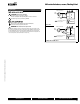
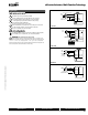
1. Remove an
y
protective fl ange covers from the valve.
2. Inspect the valve to be certain the waterwa
y
is free from dirt and
foreign matter. Be certain the adjoining pipeline is free from any
forei
g
n material such as rust and pipe scale or weldin
g
sla
g
that
could damage the seat and disc sealing surfaces
.
3
.
A
ny actuator s
h
ou
ld
b
e mounte
d
on t
h
e va
l
ve pr
i
or to
i
nsta
ll
at
i
on to
facilitate proper ali
g
nment of the disc in the valve seat.
4.
C
heck the valve identifi cation tag for materials, and operating
pressure to be sure they are correct for the application.
I
n
s
t
alla
t
io
n
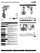
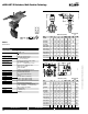
Reco
mm
e
n
da
t
io
n
s
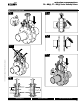
F6…HD
(
U
)
, F7…HD
(
U
)
S
eries Butter
fl
y Valve
s
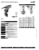
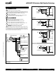
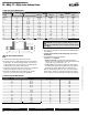
FLANGE BOLTING RECOMMENDATIONS
Flange Detail for ANSI B16.5 Pipe Flanges
FLAN
G
E
S
D
RILLIN
G
BO
LTIN
G
Nominal
Pipe Siz
e
A
Flan
g
e Diameter
B
Flan
g
e Thickness
C
Diameter o
f
Bolt
C
i
rcl
e
D
D
iameter of
Bolt Holes
Number
o
f Bolts
D
iamete
r
of Bolts
2
”
6” 3
/
4”
4
-3
/
4”
3/
4”
4
5
/
8
”
2-1/2” 7” 7/8” 5-1/2”
3
/4”
4
5/8
”
3”
7-1/2” 15/16
”
6”
3
/4”
4
5/8
”
4
”
9” 15
/
16
”
7
-1
/
2”
3/
4”
8
5
/
8
”
5”
1
0
” 15/16
”
8-1/2”
7
/8”
8
3/4
”
6”
11” 1”
9
-1
/
2”
7/
8”
8
3
/
4
”
8”
13-1/2” 1-1/8
”
11-3/4”
7
/8”
8
3/4
”
10
”
16” 1-3/16
”
14-1/4”
1
” 1
2
7/8
”
12” 19” 1-1/4
”
17”
1
”1
2
7/8
”
14” 21” 1-3
/
8
”
18-3
/
4” 1-1
/
8” 1
2
1
”
16”
23
-
1/2”
1
-7
/16”
21
-
1/4”
1
-
1/8”
16
1”
18” 25” 1-5/8
”
2
2-3/4” 1-1/4” 1
6
1-1/8”
20”
2
7-
1/2”
1
-
11/16”
2
5
”
1
-
1/4”
20
1
-
1/8”
24”
32”
1
-7
/8
29
-
1/2”
1
-
3/8”
20
1
-
1/4”
WARNING! Personal injur
y
or propert
y
damage ma
y
resul
t
if
t
h
e va
l
ve
i
s
i
nsta
ll
e
d
w
h
ere serv
i
ce con
di
t
i
ons cou
ld
excee
d
t
he
v
alve ratings.
5
. Check the fl an
g
e bolts or studs for proper size, threadin
g
, and len
g
th.
6
. These valves are designed to be installed between A
S
ME/AN
S
I
C
lass
1
25/150 fl an
g
es.
7
. Carefull
y
follow installation using welded fl anges on page 82 of
thi
s
d
ocument.
8. Follow ASME fl an
g
e ali
g
nment standards:
S
E
C
TI
O
N 335.1.1 ALI
G
NMENT
a
.
P
IPIN
G
DI
S
T
O
RTI
O
N
S
: Any distortion of piping to bring into
alignment
f
or
j
oint assembl
y
which introduces a detrimental strain
i
n equ
i
pment or p
i
p
i
ng components
i
s pro
hibi
te
d
.
b
. FLAN
G
E J
O
INT
S:
Before boltin
g
up, fl an
g
e faces shall be ali
g
ned
to the design plane within 1/16”/
f
t measured across any diameter;
fl ange bolt holes shall be aligned within 1/8” maximum offset.
9
. When observed during assembl
y
, the
fl
ange
f
aces shall be parallel
w
ithin 1 de
g
ree, and the
f
orce required to ali
g
n pipe axes shall not
exceed 10 lb/ft per inch of NF bolts and nuts shall be fully engaged.