
Manual

800-543-9038 USA 866-805-7089 CANADA 203-791-8396 LATIN AMERICA
3
7
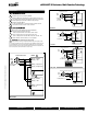
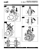
Wiring Diagrams
3
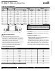
Actuators may also be powered by 24 VDC.
5
Actuators with
p
lenum rated cable do not have numbers on wires; use
c
olor coded instead. Actuators with a
pp
liance rated cable use numbers
.
8
Control signal may be pulsed from either the Hot (Source) o
r
Common
(
Sink
)
24 VAC line
.
10
For triac sink the Common connection from the actuator must be
c
onnected to the Hot connection o
f
the controller.
M
eets cULus or UL and
CS
A requirements without the
need of an electrical
g
round connection.
9
C
ontact closures A & B also can be triacs. A & B should
both be closed
f
or triac source and open
f
or triac sink
.
11
P
osition
f
eedback cannot be used with a Triac sink controller. The
actuator internal common re
f
erence is not compatible
.
W
ARNIN
G
L
ive Electrical
C
omponents
!
During installation, testing, servicing and troubleshooting of this product, it may
be necessary to work with live electrical components. Have a quali
fi
ed licensed electrician
o
r other individual who has been properl
y
trained in handling live electrical components
p
er
f
orm these tasks. Failure to
f
ollow all electrical sa
f
et
y
precautions when exposed to live
e
l
ectr
i
ca
l
components cou
ld
resu
l
t
i
n
d
eat
h
or ser
i
ous
i
n
j
ur
y
.
G
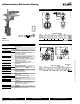
MX24-MFT-X1 Actuators, Multi-Function Technolog
y
7
Blk (1) Common
Red
(2) + Hot
Wht
(3) Y
1
Input, 2 to 10V
Org (5) U Output, 2 to 10V
4 to 20 mA
or
2 to 10 VDC
Control Signal
Line
Volts
24 VAC Transformer
(+)
(–)
Ω
500Ω
1/4 watt
3 5
CCW CW
W
545_No_
2
V
D
C/
4-20 mA
Blk (1) Common
Red
(2) Hot
Wht
(3) Y Input
Org
(5) U Output
Line
Volts
24 VAC/DC Transformer
a
Position
Feedback VDC
(+)
(–)
3
W545_No_
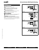
2
T
w
o
Po
s
i
t
ion
CCW
CW
AB
5
CCW
CW
AB
5
Direction of rotation switch
Line
Volts
2 to 10 VDC
Feedback Signal
24 VAC Transformer
Blk
(1) Common –
Red
(2) Hot +
Wht
(3) Y
1
Input
Org
(5) U Output 2 to 10V
Pnk (4) Y
2
Input
8
3
A
B
9
10
11
W545_No_2
F
loatin
g
Point
Blk (1) Common
Red
(2) + Hot
Wht
(3) Y Input
Org (5) U Output
Line
Volts
24 VAC Transformer (AC only)
(+)
(–)
8
Position
Feedback VDC
W
545_No_2
PWM
Blk (1) Common
Red (2) + Hot
Wht (3) Y
Input, 2 to 10 V
Org (5) U Output 2 to 10 V
CCW CW
Master
CCW CW
Slave
24 VAC Transformer
Line
Volts
Control Signal
2 to 10 VDC
(–)
(+)
3
5
Blk (1) Common
Red (2) + Hot
Wht (3) Y
Input, 2 to 10 V
Org (5) U
5
Master
_S
lav
e
Master
/S
lave
0
7/10 - Subject to change. © Belimo Aircontrols
(
USA
)
, Inc
.