
Manual

800-543-9038 USA 866-805-7089 CANADA 203-791-8396 LATIN AMERICA
3
6
Model
s
G
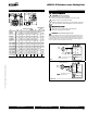
MX24-MFT-X1
Technical Data
Power suppl
y
24 VA
C
± 20% 50
/
60 Hz
24 VD
C
± 10%
P
ower consum
p
t
i
on runn
i
n
g
4
.5
W
h
o
ldi
ng
2
W
Transformer sizin
g
7 VA
(
class 2 power source
)
El
ectr
i
ca
l
connect
i
o
n
3 ft, 18
G
A appliance cable,
1/2”
con
d
u
i
t connector
O
verload protectio
n
e
l
ectron
i
c t
h
roug
h
out
0
to
9
5
°
rotat
i
on
Control si
g
nal 2 to 10 VDC
,
4 to 20 mA
(
w
i
t
h
5
00
Ω
, 1/4 W resistor) Z
G
-R01
I
n
p
ut
i
m
p
e
d
ance
100
k
Ω
for 2 to 10VD
C
(
0.1 mA
)
500
Ω
f
or 4 to 20 mA
7
50
Ω
fo
r PWM
1
5
00
Ω
f
or on/o
ff
and
fl
oating poin
t
Angle o
f
rotation
m
ec
h
an
i
ca
ll
y
li
m
i
te
d
to
9
5
°
Direction o
f
rotation reversible with switch A
/B
P
o
si
t
i
on
i
n
di
cat
i
o
n
0
to
1
an
d
rever
sibl
e
i
n
di
cato
r
R
unn
i
ng t
i
me
1
5
0
sec
.
Humidity 5 to 95% RH non-condensing
Ambient tem
p
erature
-
22°F to 122°F
[
-30°C to 50°C
]
S
tora
g
e temperature
-
40°F to 176°F
[
-40°
C
to 80°
C]
H
ous
i
ng
NEMA
2/IP
5
4
H
ous
i
ng mater
i
a
l
UL94-5VA
(
fl ammability rating
)
A
genc
y
li
st
i
ng
s
c
UL
us accor
di
ng to
UL60
7
30
-
1A/
-
2
-
14
,
C
AN/
CS
A E60730-1,
CS
A
C
22.2 No.24-93,
C
E according to 89/336/EE
C
N
o
is
e
l
eve
l
m
ax. 45 d
B
(A)
Servicin
g
m
aintenance
f
re
e
Q
ualit
y
standar
d
I
SO
9001
G
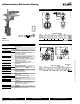
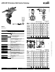
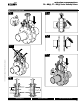
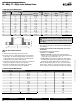
MX24-MFT-X1 Actuators, Multi-Function Technolo
gy
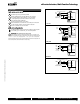
Dimensions with 2-Way Valve
D
B
C
A
BHC
Dimensions
(
Inches
)
Non-Fail Safe
(
psi
)
V
a
l
ve
S
ize
A
B
C
D
(
Max
)
B
H
C
G
M
2
*
GM
F
680HD
3”
1.69 9.00 9.00 20.50 6.00 200
F6100HD
4”
1
.
92
9
.
00
9
.
00
21
.
00
7
.5
0
200
F6100HDU
4”
1
.
92
9
.
00
9
.
00
21
.
00
7
.5
0
5
0
F612
5
HDU
5
”
2
.
08
9
.
00
9
.
00
22
.
00
8
.5
0
5
0
F
6150HD
U
6”
2.
08
9
.
00
9
.
00
22.
50
9
.
50
50
F
650-150
S
HP
2”
1
.75
9
.
00
9
.
00
19
.5
0
4
.75
28
5
F
665-150
S
HP
2½”
1
.
88
9
.
00
9
.
00
20
.
00
5.5
0
28
5
F
680-150
S
HP
3”
1.9
2
9.00 9.00 20.50 6.00 285
F
6100-150
S
HP
4”
2
.
13
9
.
00
9
.
00
21
.
00
7
.5
0
1
5
0
285
F
650-300
S
HP
2”
1.75 9.00 9.00 19.50 5.00 285 40
0
F
665-300
S
HP
2½”
1
.
88
9
.
00
9
.
00
20
.
00
5.
88
28
5
400
F
680-300
S
HP
3”
1.
92
9
.
00
9
.
00
2
0
.
50
6
.
63
2
85
4
00
F
6100-300
S
HP
4”
2
.
13
9
.
00
9
.
00
21
.
00
7
.
88
1
5
0
285
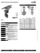
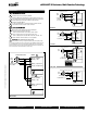
Dimensions with 3-Way Valve
1
0
0
1
0
0
D
AB
C
D
imensions
(
Inches
)
Non-Fail
S
afe
(
psi
)
V
a
l
ve
S
ize
A
B
C
D
(
Max
)
B
H
C
G
M
2
*
G
M
F
765HD
2½
”
5
.00 6.70 6.70 16.00 5.50 200
F
7
80HD
3”
5
.5
0
7.
20
7.
20
16
.
2
5
6
.
00
200
F
7
80HDU
3”
5
.5
0
7.
20
7.
20
16
.
2
5
6
.
00
5
0
F
7
100HD
4”
6
.5
0
8
.
4
5
8
.
4
5
1
7.
00
7
.5
0
200
F
7
100HDU
4”
6
.5
0
8
.
4
5
8
.
4
5
1
7.
00
7
.5
0
50
F
7125HD
U
5
” 7.
50
9
.
60
9
.
60
17.
50
8
.
50
50
F
7
1
5
0HDU
6”
8
.
00
10
.
08
10
.
08
18
.
00
9
.5
0
50
F
750-150
S
HP 2” 4.50 6.25 6.25 16.50 4.75 150 285
F
765-150SHP
2
½”
5
.00 6.88 6.88 17.00 5.50 150 285
F
780-150
S
HP 3”
5
.50 7.42 7.42 17.50 6.00 150 285
F
7100-150
S
HP 4” 6.50 8.63 8.63 18.00
7
.50 150
F
750-300SHP 2”
5
.00 6.75 6.75 15.50 5.00 285
F
765-300
S
HP
2
½”
5
.50 7.38 7.38 16.00 5.88 285
F
780-300
S
HP 3” 6.00 7.92 7.92 16.25 6.63 285
F
7100-300
S
HP 4” 7.00 9.13 9.13 18.00
7
.88 150
A
M_GM_LineRevise
d
D
101
0
7/10 - Subject to change. © Belimo Aircontrols (USA), Inc.