
Manual

800-543-9038 USA 866-805-7089 CANADA 203-791-8396 LATIN AMERICA
31
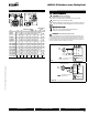
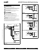
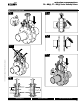
Wiring Diagrams
2
C
A
U
TI
ON
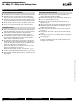
Equipment damage
!
Actuators ma
y
be connected in parallel
.
P
ower consumpt
i
on an
d
i
nput
i
mpe
d
ance must
b
e o
b
serve
d
.
4
Actuators ma
y
also be powered b
y
24 VDC
.
Meets cULus or UL and CSA requirements without the
need o
f
an electrical ground connection.
W
ARNIN
G
L
ive Electrical Com
p
onents
!
During installation, testing, servicing and troubleshooting of this product, it may
be necessary to work with live electrical components. Have a qualifi ed licensed electrician
or other individual who has been properl
y
trained in handling live electrical components
per
f
orm these tasks. Failure to
f
ollow all electrical sa
f
ety precautions when exposed to live
e
lectrical components could result in death or serious in
j
ur
y
.
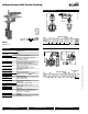
AM
S
eries Actuators,
O
n
/Off
, Floating Point
jy
2 3 5
24 VAC Transformer
a open
a closed
Blk (1) Common
Red (2) +
Wht (3) +
a
Line
Volts
The indication of direction
is valid for switch position 1.
AMB24-3-X1
10
W557
_
10
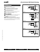
O
n
/
Off control
24 VAC Transformer
Blk (1) Common
Red (2) +
Wht (3) +
Line
Volts
The indication of direction
is valid for switch position 1.
2 3 5
AMB24-3-X1
10
W557
_
1
0
F
loating Point or On/Off contro
l
0
7/10 - Subject to change. © Belimo Aircontrols
(
USA
)
, Inc
.