
Manual

800-543-9038 USA 866-805-7089 CANADA 203-791-8396 LATIN AMERICA
27
G
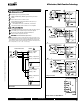
KB24-3-X1 Actuators,
O
n
/Off
, Floating Point
W
399_10
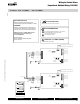
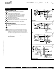
On/Off control
Off l
W399_10
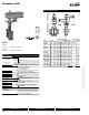
F
loat
i
n
g
Po
i
nt contro
l
Wiring Diagrams
1
P
rovide overload
p
rotection and disconnect as required.
3
A
ctuators ma
y
also be powered b
y
24 VDC.
4
P
o
s
ition feedback cannot be u
s
ed with Triac
s
ink controller
.
The actuator internal common reference is not compatible.
5
C
ontrol signal may be pulsed from either the Hot (source)
or the
C
ommon (sink) 24 VA
C
line
.
8
C
ontact closures A & B also can be triacs
.
A
& B should both be closed for triac source and open for triac sink.
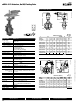
9
Fo
r tri
ac
s
ink th
e
co
mm
o
n
co
nn
ec
ti
o
n fr
o
m th
e
ac
t
ua
t
o
r
mu
s
t be connected to the hot connection of the controller.
Meets UL requirements without the need of an electrical ground
connect
i
on.
WARNING
Live Electrical Components!
G
D
urin
g
installation, testin
g
, servicin
g
and troubleshootin
g
o
f
this product, it
m
ay be necessary to work with live electrical components. Have a quali
fi
ed
li
cense
d
e
l
ectr
i
c
i
an or ot
h
er
i
n
di
v
id
ua
l
w
h
o
h
as
b
een proper
l
y tra
i
ne
d
i
n
h
andling live electrical components perform these tasks. Failure to follow all
electrical sa
f
ety precautions when exposed to live electrical components could
r
esult in death or serious injury
.
N
O
TE: Wiring diagrams shown are for single actuator
mounted solutions
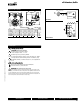
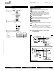
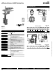
Electrical Installation
Wi
r
i
ng
di
agram
Y
U
1
3
2
5
– +
T
~
C
able colors
:
1
= bla
c
k
2 =
re
d
3
= whi
t
e
5
= orang
e
C
able lengths
Y
U
1
3
2
5
T
~
A
C
L
1
L
2
L
t
o
t
A
=
A
ctuator
C
=
C
ontrol unit
L
1
=
Belimo connecting cable, 1 m
(
4 x 0.75 m
m
2
)
L
2
=
C
u
s
to
me
r
cab
l
e
L
to
t
=
M
ax
i
mum ca
bl
e
l
engt
h
C
ross sectio
n
L
2
T
/
~
Max. cable len
g
t
h
L
t
o
t
=
t
L
1
+
L
2
Exam
p
le for D
C
A
C
DC
0.75 m
m
2
<
30
m
<
5
m1
m
(
L
1
)
+ 4 m
(L
2
)
1.00 m
m
2
<
40
m
<8
m1
m
(
L
1
)
+ 7 m
(L
2
)
1.50 m
m
2
<
70
m
<
12
m1
m
(
L
1
)
+ 11 m
(L
2
)
2.50 m
m
2
<
100 m
<
20
m1
m
(
L
1
)
+ 19 m
(L
2
)
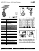
L
N
Y
U
T
1
3
2
5
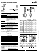
A
C
A
AC
A
2
4
V
V
V
AC
C
C
230
V
V
L
1
A
=
A
ctuato
r
C
=
C
ontrol unit
L
1
=
Belimo connecting cable, 1 m (4 x 0.75 mm
2
m
m
)
N
o
te
•
C
onnect via s
a
fe
t
y
isolation tran
s
fo
r
mer
.
•
P
arallel connection o
f
other actua
t
o
rs
p
oss
ibl
e.
No
t
e
p
e
r
fo
rm
a
n
ce
da
t
a
fo
r suppl
y
.
!
DC
0 ... 10 V
D
C 2 ... 10 V
N
o
t
e
Wh
e
n
se
ve
ra
l
ac
t
uat
o
r
s
ar
e
co
nn
ect
e
d in
p
arallel,
t
h
e max
i
mum ca
bl
e
l
engt
h
must
b
e
di
v
id
e
d
b
y t
h
e
n
umber o
f
actua
t
or
s.
No
t
e
Th
e
r
e a
r
e no spec
i
a
l
re
s
trictions on installation i
f
the suppl
y
and data cable a
r
e
rou
t
ed se
p
ara
t
e
l
y.
0
7/10 - Subject to change. © Belimo Aircontrols
(
USA
)
, Inc
.