
Manual

800-543-9038 USA 866-805-7089 CANADA 203-791-8396 LATIN AMERICA
2
5
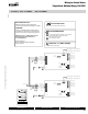
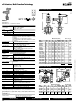
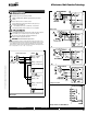
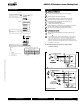
Wiring Diagrams
3
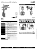
Actuators may also be powered by 24 VDC.
4
IN4004 or IN4007 diode (IN4007 supplied,
B
elimo part number
40155).
5
Triac A and
B
can al
s
o be contact clo
s
ure
s
.
6
C
ontrol signal may be pulsed from either the Hot (
S
ource) or
C
ommon (
S
ink) 24 VA
C
line
.
7
P
o
s
ition feedback cannot be u
s
ed with Triac
s
ink controller.
The actuators internal common reference is not compatible.
The Z
G
-R01 500 Ω resistor converts the 4 to 20 mA control signal to
2
to 10 VDC, up to 2 actuators ma
y
be connected in parallel.
M
eets cULus or UL and CSA re
q
uirements without the
need of an electrical ground connection.
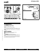
W
ARNIN
G
Live Electrical Components
!
During installation, testing, servicing and troubleshooting of this product, it may
be necessar
y
to work with live electrical components. Have a qualifi ed licensed electrician
o
r other individual who has been properl
y
trained in handling live electrical components
p
erform these tasks. Failure to follow all electrical safet
y
precautions when exposed to live
e
l
ectr
i
ca
l
components cou
ld
resu
l
t
i
n
d
eat
h
or ser
i
ous
i
n
j
ury.
AF Actuators, Multi-Function Technolog
y
W399_Butter
f
ly
VD
C/
4-2
0
m
A
W399_Butter
f
ly
PWM
M
W
399_Butter
f
l
y
On/Off control
Off l
W
399_Butter
f
l
y
Float
i
ng Po
i
nt contro
l
AFB24-MFT-S
AFX24-MFT-S
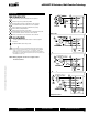
Auxiliary Switches for AFX24-MFT-S-X
1
W
600_
AFB
_
AFX
1
A
FX24-MFT-
S
-X
1
1
Blk (1) Common
Red (2) + Hot
Wht (3) Y
Input, 2 to 10 V
Org (5) U Output 2 to 10 V
CCW CW
Master
CCW CW
Slave
24 VAC Transformer
Line
Volts
Control Signal
2 to 10 VDC
(–)
(+)
3
5
Blk (1) Common
Red (2) + Hot
Wht (3) Y
Input, 2 to 10 V
Org (5) U
5
Master
_S
lave
M
as
t
e
r
/S
l
a
v
e
0
7/10 - Subject to change. © Belimo Aircontrols
(
USA
)
, Inc
.