
Manual

800-543-9038 USA 866-805-7089 CANADA 203-791-8396 LATIN AMERICA
2
3
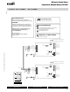
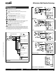
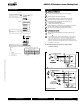
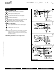
Wiring Diagrams
2
C
A
U
TI
ON
Equipment dama
g
e
!
Actuators may be connected in parallel
.
P
ower consumpt
i
on must
b
e o
b
serve
d
.
3
Actuators ma
y
also be powered b
y
24 VDC
.
4
For end
p
osition indication, interlock control, fan startu
p
, etc., AF24-
S
US incorporates two built-in auxiliary switches: 2 x SPDT, 7A
(
2.5A
)
@ 250 VA
C
, UL listed, one switch is fi xed at +5°, one is adjustable 25°
to
8
5
°
.
Meets cULus or UL and
CS
A re
q
uirements without the
need of an electrical
g
round connection.
W
ARNIN
G
L
ive Electrical Com
p
onents
!
During installation, testing, servicing and troubleshooting of this product, it may
be necessar
y
to work with live electrical components. Have a qualifi ed licensed electrician
or ot
h
er
i
n
di
v
id
ua
l
w
h
o
h
as
b
een proper
l
y tra
i
ne
d
i
n
h
an
dli
ng
li
ve e
l
ectr
i
ca
l
components
perform these tasks. Failure to follow all electrical safet
y
precautions when exposed to live
e
lectrical components could result in death or serious in
j
ur
y
.
A
F Actuators, On/Of
f
1 Common
2 + Hot
2
24 VAC Transformer
AF24 US
Line
Volts
3
pjy
W
1
94
O
n/Off Wiring
W195-A
U
X
A
uxiliar
y
Switche
s
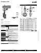
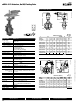
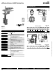
Dimensions with 3-Way Valve
10
10
D
AB
C
Dimensions (Inches)
F
ail Safe (psi
)
V
a
l
v
e
Size
A
B
C
D
(Max) BHC
AF
2*AF
F
75
0HD
2”
4
.5
0
6
.
1
5
6
.
1
5
1
5.5
0
4
.75
200
F750HDU
2
” 4.50 6.15 6.15 15.50 4.75 5
0
F
7
6
5
HD
2½”
5.
00
6
.7
6
6
.7
6
16
.
00
5.5
0
200
F765HD
U
2½” 5.00 6.76 6.76 16.00 5.50 5
0
F
7
80HDU
3”
5.5
0
7.
28
7.
28
16
.
2
5
6
.
00
5
0
HS
DW
G
P11
0
7/10 - Subject to change. © Belimo Aircontrols
(
USA
)
, Inc
.