
Manual

800-543-9038 USA 866-805-7089 CANADA 203-791-8396 LATIN AMERICA
1
5
Wirin
g
for Damper Actuators and Control Valves
Pro
p
ortional
,
24V
,
120
/
230
V
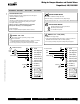
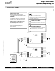
Each actuator should be powered by a single, isolated
control transformer.
s0OWERSUPPLY#OM.EUTRALAND#ONTROL3IGNAL "–" wiring to a common is
prohibited. Terminals 4 and 6 need to be wired separately.
s$ONOTCHANGESENSITIVITYORDIPSWITCHSETTINGSWITHPOWERAPPLIED
/BSERVE#LASSAND#LASSWIRINGRESTRICTIONS
4RANSFORMERSIZING39ACTUATORDRAW8SAFETYMARGIN
%X39REQUIRES!X!!86!#6!4RANSFORMER
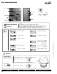
Indicates an action or condition that may cause irreversible
damage to the actuator(s) or associated equipment.
%QUIPMENTDAMAGE
0OWERCONSUMPTIONANDINPUTIMPEDANCEMUSTBEOBSERVED
CAUTION
)NDICATESAPOTENTIALLYHAZARDOUSSITUATIONWHICHIFNOTAVOIDED
may result in minor or moderate injury. It may also be used to
alert against unsafe practices.
7ARNINGSAND#AUTIONSAPPEARATAPPROPRIATESECTIONSTHROUGHOUT
this manual. Read these carefully.
Hazard Identification
33
33
INSTALLATION NOTES
Use of feedback is optional.
APPLICATION NOTES
36
34
Ground shielded wire at control panel chassis.
Tape back ground at actuator.
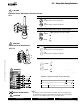
NOTES SY1…24P
24 VAC Transformer
Line
Volts
G Ground
4 Power Supply Com
5 Power Supply Hot
6 Control Signal (-)
7 Control Signal (+)
8 Internal Use Only
9 Internal Use Only
10 Internal Use Only
11 Feedback (-)
12 Feedback (+)
Feedback
Control signal
G
SY1-24P
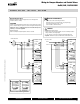
A
B
C
E
F
#ONTACT2ATING !6!#-AX
!6!#-AX
!"/PEN)NDICATION
LS4
LS3
!%#LOSED)NDICATION
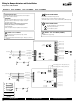
G Ground
4 Power Supply Com
5 Power Supply Hot
6 Control Signal (-)
7 Control Signal (+)
8 Internal Use Only
9 Internal Use Only
10 Internal Use Only
11 Feedback (-)
12 Feedback (+)
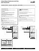
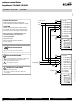
120 and 230 VAC
N L1
H L2
SY1 -110P (220P)
A
B
C
E
F
#ONTACT2ATING !6!#-AX
!6!#-AX
!"/PEN)NDICATION
LS4
LS3
!%#LOSED)NDICATION
NOTES SY1…110P (220P)
sCaution:0OWERSUPPLYVOLTAGE
s0OWERSUPPLY#OM.EUTRALAND#ONTROL3IGNAL "–" wiring to a common is
prohibited. Terminals 4 and 6 need to be wired separately.
s$ONOTCHANGESENSITIVITYORDIPSWITCHSETTINGSWITHPOWERAPPLIED
Control signal
Feedback
G
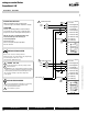
34
36
34
36
W
547
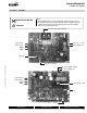
Actuators: SY1-24P SY1-110P SY1-220P
0
7/10 - Subject to change. © Belimo Aircontrols
(
USA
)
, Inc
.