
User Manual

800-543-9038 USA 866-805-7089 CANADA 203-791-8396 LATIN AMERICA
63
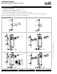
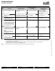
AF24-SR US Electrical Check-out Procedure
S
TEP Pr
ocedu
r
e
Expected Response
G
ives Ex
p
ected Res
p
onse
G
o To Step…
D
oes Not Giv
e
Expected Response
Go To Ste
p
…
1
.
C
ontrol signal is applied to actuator. Actuator will move to its “
C
ontrol
S
ignal” position
.
A
ctuator operates properly
S
tep 7. No response at all
S
tep 2
.
O
p
eration is reversed Ste
p
3.
Does not drive toward "Control Signal
Position" Step 4.
2.
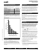
Check power wiring
.
Correct an
y
p
roblems.
See
N
o
t
e
1
.
Power supply rating should be the total
power requirement of the actuator(s).
Minimum volta
g
e of 19.2 VAC or 21.6 VDC.
P
ower wiring corrected, actuator
b
eg
i
ns to
d
r
i
ve Ste
p
1.
Power wiring corrected, actuator still
d
oes not
d
r
i
ve Ste
p
4.
3.
Turn reversing switch to the correct
pos
i
t
i
on.
M
a
k
e sure t
h
e sw
i
tc
h
i
s
turned all the way left or ri
g
ht.
Actuator will move to its “Control
S
ignal” position
.
A
ctuator operates properly
S
tep 7. Does not drive toward “Control Signal
P
os
i
t
i
on
”
S
tep 4
.
4
.
M
a
k
e sure t
h
e contro
l
s
i
gna
l
pos
i
t
i
ve
(+) is connected to Wire No. 3 and
control si
g
nal ne
g
ative
(
-
)
is connected
to wire No. 1. Most control problems
are cause
d
b
y revers
i
ng t
h
ese two
wires. Verify that the reversing switch
is all the wa
y
CCW or CW.
Drives to “
C
ontrol
S
ignal” position
.
A
ctuator operates proper
l
y
S
tep 7.
Step 5.
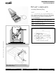
5.
Check input signal with a digital volt
meter
(
DVM
)
. Make sure the input
is within the ran
g
e o
f
the actuator. For
A
F24-
S
R U
S
this is 2 to 10 VD
C
or 4 to
20 mA
.
N
O
TE
:
The input si
g
nal must be
above the 2 VDC or 4 mA to have
the actuator move.
Input voltage or current should be ±1%
o
f
what controller's ad
j
ustment or
pro
g
rammin
g
i
n
di
cate.
C
ontroller output (actuator input)
i
s correct. Input Polarity Correct
S
tep 6.
Reprogram, adjust repair or replace
controller as needed Step 1.
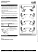
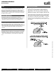
7.
C
heck damper torque requirement
.
T
orque requ
i
rement
i
s actuator
’
s
m
inimum tor
q
ue
.
D
e
f
ective Actuator
.
R
e
p
lace Actuator -
S
ee N
o
te 2.
R
eca
l
cu
l
ate actuator requ
i
rement an
d
correct installation.
8
.
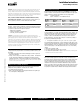
A
ctuator wor
k
s proper
l
y.
T
est
controller by following controller
manufacturer's instructions
.
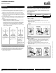
NOTE
1
Check that the transformer(s) are sized properly.
• If a common transformer is used, make sure that polarity is observed on the secondary. This means connect all No. 1 wires to one le
g
of the transformer and all
N
o. 2 wires to the other le
g
of the transformer.
• I
f
multiple trans
f
ormers are used with one control signal, make sure all No. 1 wires are tied together and tied to control signal negative (-).
• Controllers and actuators must have separate 24 VAC/VDC power sources
.
N
O
TE
2
If failure occurs within 5 years from ori
g
inal installation date, notify Belimo and
g
ive details of the application.
Startup and Checkou
t
Instructi
o
ns F
o
r AF24-SR U
S
M40024 - 05/10 - Subject to change. © Belimo Aircontrols (USA), Inc.