
User Manual

800-543-9038 USA 866-805-7089 CANADA 203-791-8396 LATIN AMERICA
6
2
WARNING The wiring technician must be trained and experienced with electronic
circuits. Disconnect power supply before attempting any wiring connections or
changes. Make all connections in accordance with wiring diagrams and follow all
applicable local and national codes. Provide disconnect and overload protection as
required. Use copper, twisted pair, conductors only. If using electrical conduit, the
attachment to the actuator must be made with flexible conduit.
Alwa
y
s read the controller manufacturer's installation literature carefull
y
b
efore makin
g
any connections. Follow all instructions in this literature. If you
have an
y
q
uestions, contact the controller manufacturer and/or Belimo.
Transformers
The AF24 . . actuators re
q
uire a 24 VA
C
class 2 transformer and draws a maximum
o
f 10 VA per actuator. The actuator enclosure cannot be opened in the field, there
a
re no
p
arts or com
p
onents to be re
p
laced or re
p
aired.
– EMC directive: 89/336/EEC
– Software class A: Mode of operation type 1
– Low volta
g
e directive: 73/23/EEC
CAUTION: It is good practice to power electronic or digital controllers from a
separate power transformer than that used for actuators or other end devices. The
power supply design in our actuators and other end devices use half wave
rectification. Some controllers use full wave rectification. When these two different
types of power supplies are connected to the same power transformer and the DC
commons are connected together, a short circuit is created across one of the diodes
in the full wave power supply, damaging the controller. Only use a single power
transformer to power the controller and actuator if you know the controller power
supply uses half wave rectification.
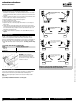
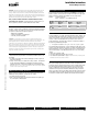
Multiple Actuators, One Transformer
M
ultiple actuators may be powered from one transformer provided the followin
g
rules
a
r
e
f
o
ll
o
w
ed
:
1
. The TOTAL current draw of the actuators (VA rating) is less than or equal to the
ratin
g
o
f
the trans
f
ormer
.
2. Polarit
y
on the secondar
y
of the transformer is strictl
y
followed.
T
his means tha
t
a
ll No. 1 wires
f
rom all actuators are connected to the common le
g
on th
e
t
rans
f
ormer and all No. 2 wires
f
rom all actuators are connected to the hotle
g
.
Mixing wire No. 1 & 2 on one leg of the transformer will result in erratic operation
or failure of the actuator and/or controls.
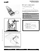
Multiple Actuators, Multiple Transformers
M
ultiple actuators positioned by the same control si
g
nal may be powered
f
rom
multiple trans
f
ormers provided the
f
ollowing rules are
f
ollowed:
1
. The trans
f
ormers are
p
ro
p
erl
y
sized
.
2. All No. 1 wires
f
rom all actuators are tied together and tied to the negative leg o
f
the control signal.
S
ee wiring diagram.
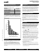
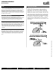
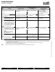
Wire Length for AF... Actuators
Keep power wire runs below the lengths listed in the Figure
H
.
If m
o
r
e
th
a
n
o
n
e
actuator is powered
f
rom the same wire run, divide the allowable wire length by the
n
umber o
f
actuators to determine the maximum run to any single actuator.
Example: 3 actuators, 16 Ga wire
350 Ft ÷ 3 Actuators = 117 Ft. Maximum wire ru
n
M
AXIMUM WIRE LENGTH FOR 10V
A
W
ire
S
ize
M
ax.
F
eet.
W
ire
S
ize
M
ax.
F
eet
12 Ga 900 Ft.
1
8 Ga 220 Ft
.
14
Ga
550
Ft.
20
Ga
1
2
0
Ft.
1
6
Ga
350
Ft.
2
2
Ga
60
Ft
.
FI
GU
RE
H
Wire Type and Wire Installation Tips
For most installations
,
18 or 16 Ga. cable works well with the AF24... actuators. Use
co
d
e-approve
d
w
i
re nuts, term
i
na
l
str
i
ps or so
ld
er
l
ess connectors w
h
ere w
i
res are
joined. It is good practice to run control wires unspliced
f
rom the actuator to the
controller. I
f
splices are unavoidable, make sure the splice can be reached
f
or
p
ossible maintenance. Ta
p
e and/or wire-tie the s
p
lice to reduce the
p
ossibilit
y
of
t
h
e sp
li
ce
b
e
i
n
g
i
na
d
vertent
l
y pu
ll
e
d
apart
.
Th
e
AF
24... proport
i
ona
l
actuators
h
ave a
di
g
i
ta
l
c
i
rcu
i
t t
h
at
i
s
d
es
i
gne
d
to
i
gnore
most unwanted input signals (pickup). In some situations the pickup may be severe
enou
g
h to cause erratic runnin
g
of the actuator. For example, a lar
g
e inductive load
(
hi
g
h volta
g
e AC wires, motors, etc.
)
runnin
g
near the power or control wirin
g
may
cause excessive pickup. To solve this problem, make one or more of the followin
g
c
h
anges:
1. Run the wire in metallic conduit
.
2. Re-route the wirin
g
away
f
rom the source o
f
pickup
.
3. Use shielded wire
(
Belden 8760 or equal
)
. Ground the shield to an earth ground.
Do not connect it to the actuator common.
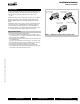
Initialization of the AF24-SR US
When power is initially applied, the actuator will
f
irst release its manual preload
p
osition
(
This assumes a manual position has been set
)
. The actuator will then rotate
to the full fail-safe position. At this point the microprocessor recognizes that the
actuator is at full fail-safe and uses this
p
osition as the base for all of its
p
osition
calculations. The microprocessor will retain the initialized zero durin
g
short power
f
ailures o
f
up to 20 seconds. For power
f
ailures
g
reater than 20 seconds, the actuator
would naturally return to its full fail-safe position prior to the microprocessor losin
g
its memor
y
. The actuator will also re-initialize if the manual
p
osition mechanism is
used
.
Installation Instruction
s
G
eneral Wirin
g
Instruction
s
M40024 - 05/10 - Subject to change. © Belimo Aircontrols (USA), Inc.