
User Manual

800-543-9038 USA 866-805-7089 CANADA 203-791-8396 LATIN AMERICA
59
I
n
s
t
a
ll
a
ti
o
n In
s
tr
uc
ti
o
n
s
Mechan
i
cal Installat
i
o
n
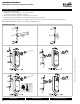
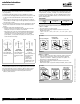
Manual Override
T
he AF series actuators can be manuall
y
p
ositioned to ease installation or
f
or
e
mer
g
ency positionin
g.
1
. The manual override will only work i
f
no power is available to the actuator.
2. Insert the manual crank (shipped with the actuator) into the hexagon hole located
on either side o
f
the actuator. An illustration, located on the label, shows the
l
oca
ti
o
n
.
3
. Turn the crank in the direction shown on the label
(
clockwise on the “CW” side,
c
ounterclockwise on the “CCW” side). It will take approximately 19 revolutions to
rotate the full 95° of rotation
.
4
. To lock the actuator in the required position, rotate the crank quickly in the opposite
direction
,
1/2 of a revolution. The “lock closed” icon on the label shows the correct
di
r
ec
t
io
n
.
5. The manual override may be disengaged in 2 ways.
-
R
o
t
a
t
e
th
e
c
r
a
nk
abou
t
a
1
/
4 r
e
v
o
l
u
ti
o
n in th
e
sa
m
e
d
ir
ec
ti
o
n
as
th
e
initi
a
l
winding. The “lock open” icon shows the correct direction.
-
Apply power to wire 1 and 2. The actuator will automatically disen
g
a
g
e the
override function and will go to the “on” position in the case of the On/Off
versions. Or, in the case of the proportional versions,
g
o to the 0 si
g
nal
position and then
g
o to the position correspondin
g
to the control si
g
nal. The
actuator will now work normall
y
.
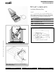
Windin
g
the
damper actuator
-
i
nsert cran
k
h
an
dl
e
-
turn handle in direction
o
f
a
rr
o
w
Lockin
g
the
damper actuator
-
rotate crank handle 1
/
2
turn in the direction
shown by the “locked”
icon.
Unlockin
g
the
damper actuato
r
(
2 opt
i
ons
)
- rotate crank handle 1/4
tu
rn in th
e
d
ir
ec
ti
o
n
s
hown b
y
the
“u
nl
oc
k
ed
” i
co
n.
- remote control b
y
s
upplyin
g
power to the
u
nit f
o
r > th
a
n
3
sec.
Testing the Installation Without Power
T
he actuator/damper installation may be tested without power at the actuator. Refer
t
o the manual positionin
g
section o
f
the instructions. Move the damper to its
f
ull
non-
f
ail-sa
f
e position usin
g
the manual crank. Disen
g
a
g
e the manual position
m
echanism and have the damper go to full fail-safe position.
C
orrect any
m
echanical
p
roblems and retest
.
Auxiliary Switches
T
he AF series actuators ma
y
be ordered with 2 built-in SPDT auxiliar
y
switches used
f
or sa
f
ety inter
f
acin
g
or si
g
nallin
g
,
f
or example,
f
or
f
an start-up. The switch position
n
ear the
f
ail-sa
f
e position is
f
ixed at 5°. The other is adjustable between 25 and 85°
o
f rotation. The crank, supplied with the actuator, or a
3
mm
a
ll
e
n wr
e
n
c
h i
s
used
t
o
a
djust the switching position.
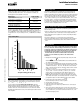
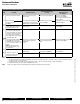
SWITCH RATING
V
oltage
R
esistive Load Inductive Load
1
2
0
VA
C
7A
5
A
250
VA
C
7A
2
.
5A
T
wo methods may be used to ad
j
ust the switchin
g
point of the ad
j
ustable switch
.
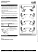
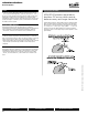
M
eth
o
d 1 - See Figure
F
1 The actuator must be in its fail-safe position.
2
. Insert the crank into the hexagon shaped hole located in the center of the
adj
usta
bl
e sw
i
tc
h
po
i
nter
.
3
.
R
otate t
h
e cran
k
unt
il
t
h
e sw
i
tc
h
po
i
nter
i
s at t
h
e
d
es
i
re
d
sw
i
tc
h
po
i
nt
i
n
d
egrees
a
s shown.
AF...
S
erie
s
30
40
50
60
70
80
25…85°
Factory setting 85°
30
40
50
60
70
80
25…85°
Rotate with
crank handle
30
40
50
60
70
80
25…85°
60° set
Crank
Handl
e
F
I
GU
RE
F
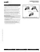
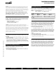
M
ethod
2
-
S
ee Figure
G
1. Position the damper to the point at which you want the switch to activate. This
may be done by using the manual override or by providing the appropriate
p
roportional si
g
nal to AF24… modulatin
g
type actuator. The position o
f
the
s
witch pointer is not important durin
g
this step
.
2
. Insert the crank into the hexa
g
on shaped hole located in the center o
f
the
a
djustable switch pointer
.
3
. Rotate the switch pointer to
j
ust past the switch point indicatin
g
arrow as shown
.
AF...
Se
ri
es
30
40
50
60
70
80
25…85°
Actuator
after locking
30
40
50
60
70
80
25…85°
Switch operates
30
40
50
60
70
80
25…85°
Switch does
not operate
Crank
Handl
e
F
IGURE G
M40024 - 05/10 - Subject to change. © Belimo Aircontrols (USA), Inc
.