
User Manual Owner's manual

AM Series Boilers and Water Heaters
CHAPTER 3 – INSTALLATION
Page 54 of 156 AERCO International, Inc. • 100 Oritani Dr. • Blauvelt, NY 10913 OMM-0100_0B
PRI - 07/14/14 Ph.: 800-526-0288 GF-146
3.14.1.1 Connecting Units in Cascade (Boilers or Water Heaters)
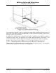
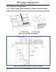
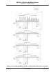
To connect the heater in cascade you have to follow the electrical connections as per Figure 3-
24. A maximum of eight heaters can be connected in a cascade (Figure 3-24 shows a
connection of four heaters).
After the electrical power connection is made, activate the BUS communication to the HC
command by performing the following:
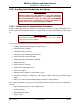
Activating the Cascade BUS Communication
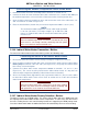
1. Access to unit interior (see Section 6.1.15).
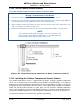
2. Move the S4 selector switch of the Burner 1 (Master) board to the OFF position. See Figure
6-12 to identify the S4 selector switch of the Burner 1 (Master) board.
3. Move the S4 selector switch of the MODBUS interface (item 13 in Figures 2-3 and 2-6), to
the ON position.
The HC Command (cascade manager) is supplied on demand. For additional information
concerning water, gas, flue exhaust, and air intake connections, contact AERCO technical
support.