
User guide


AM Series Modbus Interface Manual
CHAPTER 1: MODBUS CONNECTION
1.1 MODBUS CONFIGURATION
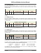
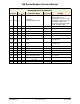
The table below summarizes the Modbus configuration details.
Modbus Configuration
Protocol
Modbus RTU
Default slave address
0x01 (settable with LabVision or by dll)
Supported Modbus
commands
Read Holding registers (0x03) Write single holding
register (0x06)
Baud rate
9600bps
Data Length
8
Parity
None
Stop Bits
2
Physical layer
RS485 (two wire + optional GND)
The default setting for the Modbus (dependent) address is 1. The address setting resides in the
e2prom of the interface and can be changed if required. This can be done using LabVision, via
the Argus link connection, or by dll.
Multiple holding registers can be read (up to all of the available registers for the device), writing
of holding registers is limited to one register at a time.
1.2 MODBUS FUNCTIONALITY
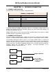
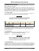
The basic modbus functionality gives control over the devices connected by their modbus
interface. The control includes building management systems, remote displays, and PLC control.
On installation, all AM Series devices must be set at a unique modbus address. To connect to
networks other than modbus, bus converters can be connected to the system. The optional bus
converter can then scans these addresses for active devices, and map them on the network it
needs to convert to. The AERCO ProtoNode Gateway can be used for conversion to BACnet,
LonWorks, Metasys N2, and Modbus TCP protocols. For further information, see the
ProtoNode Gateway user manual, GF-129.
IF
IF
XXX
Converter
(Optional)
Modbus Network
PC, or other
network BACnet,
LonWorks,
OMM-0102_0A AERCO International, Inc. • 100 Oritani Dr. • Blauvelt, NY 10913 Page 5 of 18
GF-146-MB Phone: 800-526-0288 PRI: 09/22/2014