AM Series Modbus Interface Manual Modbus Interface for AM Series Models: Water Heaters: AM 399W AM 500W AM 750W AM 1000W GF-146-MB USER MANUAL Modbus Interface For Boilers and Water Heaters Boilers: AM 399B AM 500B AM 750B AM 1000B AM Series Junction Box 485 Modbus Interface Connections Latest Update: 09/22/2014 OMM-0102_0A GF-146-MB AERCO International, Inc. • 100 Oritani Dr.
AM Series Modbus Interface Manual DISCLAIMER The information contained in this manual is subject to change without notice from AERCO International, Inc. AERCO makes no warranty of any kind with respect to this material, including, but not limited to, implied warranties of merchantability and fitness for a particular application.
AM Series Modbus Interface Manual GF-146-MB TABLE OF CONTENTS CHAPTER 1: MODBUS CONNECTION .................................................... 5 1.1 Modbus Configuration ........................................................................... 5 1.2 Modbus Functionality ............................................................................ 5 1.3 Modbus Holding Registers .................................................................... 6 1.3.1 Control Register ..................................
AM Series Modbus Interface Manual (This page intentionally blank) Page 4 of 18 PRI: 09/22/2014 AERCO International, Inc. • 100 Oritani Dr.
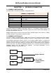
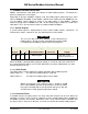
AM Series Modbus Interface Manual CHAPTER 1: MODBUS CONNECTION 1.1 MODBUS CONFIGURATION The table below summarizes the Modbus configuration details. Modbus Configuration Protocol Default slave address Supported Modbus commands Baud rate Data Length Parity Stop Bits Physical layer Modbus RTU 0x01 (settable with LabVision or by dll) Read Holding registers (0x03) Write single holding register (0x06) 9600bps 8 None 2 RS485 (two wire + optional GND) The default setting for the Modbus (dependent) address is 1.
AM Series Modbus Interface Manual 1.3 MODBUS HOLDING REGISTERS Modbus communicates using words (the contents of 16bit holding registers). The data that is offered is organized as a list of bytes. Depending on the type of Modbus software used, the holding register addressing range starts either at 0x0000 or at 0x0001. If your Modbus software starts addressing from 0x0000 you can use the holding register addresses shown in the table above.
AM Series Modbus Interface Manual 1.3.2 Controller Type For easier handling of holding registers, the data format can be changed on the modbus interface. This means that all unit conversion is done in the modbus interface (for both reading and writing data).
AM Series Modbus Interface Manual 1.3.5 Device Type In a complete bus system a lot of different devices may be connected. All these devices supply different data in their holding registers. To make a universal format for equal devices a device type is defined: Device Type Definition Device type Function 1 Managing Boiler / Stand-alone Boiler (with build in controller) 2 Dependent Boiler When reading this Device Type register, the fixed format can be found.
AM Series Modbus Interface Manual 1.4 PRE-DEFINED DEVICES 1.4.1 General Notes For all devices, empty or not, available holding registers return 0. When it is not implemented, requests can be ignored by the Modbus device. Holding registers below 99 are reserved for legacy devices, and are optional. The functionality of these registers is not changed or influenced by this specification. 1.4.
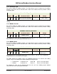
AM Series Modbus Interface Manual Managing Boiler Parameters Holding Register Access R W Parameter Name Automatic Conversion Range 123 007B X Information: (optionally implemented) 124 007C X CH pump V Bit0: On/Off - Flame Signal Bit1: Ok/Nok - Water level Bit2: Ok/Nok - Low gas pressure Bit3: Ok/Nok - High gas pressure Bit4: On/Off - Air pressure Bit5: Ok/Nok - Blocked flue Bit6: On/Off - Air damper Bit7: 0/100 or 0..100% 125 007D X DHW pump V 0/100 or 0..
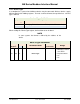
AM Series Modbus Interface Manual Controller (Managing) Parameters Access Holding Register 200 00C8 X Controller State 201 00C9 X Controller Status - See controller status table 202 00CA X Controller Error Code - See controller error list 203 00CB X Controller Warning Code - See controller warning list 204 00CC X X Controller CH setpoint V Depending on units °C / °F 205 00CD X X Controller DHW setpoint V Depending on units °C / °F 206 00CE X X High Outdoor Air tempera
AM Series Modbus Interface Manual 1.4.
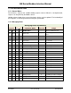
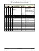
AM Series Modbus Interface Manual Dependent Boiler Parameters Access Holding Register R W 127 007F X - Ignition count Failed - 0..65536, resolution 1 128 0080 X - - 0..65536, resolution 1 129 0081 X - - 0..65536 hours 130 0082 X - Flame count Failed Burner High hours / CH hours Burner Med hours / DHW hours - 0..65536 hours 131 0083 X - Burner Low hours - 0..65536 hours - - reserved - - - - reserved - - ..
AM Series Modbus Interface Manual CHAPTER 2: ERROR, STATE, AND, STATUS TABLES 2.1 Lockout Error Codes Table Lockout errors are indicated by an ‘A’ displayed before the error code number.
AM Series Modbus Interface Manual 2.2 Blocking Error Codes Table The following errors are related to the general control functions. Blocking errors are indicated by an ‘E’ before the error code number.
AM Series Modbus Interface Manual 2.3 State Parameters Table The table below lists a detailed description of the possible values of the STATE parameter. MN States STATE Dec.
AM Series Modbus Interface Manual NOTES: OMM-0102_0A GF-146-MB AERCO International, Inc. • 100 Oritani Dr.
AM Series Modbus Interface Manual Change Log: Date 9/22/2014 Page 18 of 18 PRI: 09/22/2014 Description Rev-98 for review. AERCO International, Inc. • 100 Oritani Dr.