AEQ FORUM DIGITAL AUDIO MIXER FOR BROADCAST APPLICATIONS USER’S MANUAL ED. 04/14 V. 1.2 - 18/09/2014 Software version 3.
CONTENTS Pág. 1. INTRODUCTION............................................................................................................. 1.1. General overview…......................................................................................... 1.2. Functional specifications.................................................................................. 2. PHYSICAL DESCRIPTION OF THE UNIT...................................................................... 2.1.
.4.3.1.3. Expanded information menu………………………………. 3.4.3.1.3.1. “FADER” menu………………………………………. 3.4.3.1.3.2. “ROUTE” menu…………………………………….... 3.4.3.2. “OUTPUT” menu………………………………........................... 4. CONFIGURATION SOFTWARE….................................................................................. 4.1. “Administration” menu………………..….......................................................... 4.1.1. “Configurations” submenu................................................................... 4.1.2.
1. INTRODUCTION. 1.1. General overview. AEQ FORUM and AEQ GRAND FORUM are digital audio mixers for Broadcast applications, specifically designed for ON AIR applications and highly adaptable to different operational situations. They incorporate all the basic features needed in such environments: automatic monitors muting, cough muting, fader-start, signalling control, control signals for external equipment automation, management of external communications, intercoms, etc.
1.2. Functional specifications. • • • • • • • • • • • • • • • • Self-contained Design. Configurable size of 4, 8 or 12 faders (up to 16 or 20 faders for AEQ GRAND FORUM). Conductive plastic faders 100mm. Internal sampling rate 48 kHz to 24 bits. Variable through external clock referente. Modular design that allows you to adjust the number of inputs and outputs of the equipment to the requirements of each facility. Front removable modules for easy maintenance.
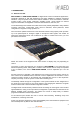
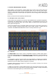
2. PHYSICAL DESCRIPTION OF THE UNIT. AEQ FORUM is a self-contained, compact digital mixing console, which means that its two functional blocks are housed in the same physical chassis. On one hand the control surface, where the controls and status indicators are located and on the other, the "audio engine" which contains all electronics for audio inputs and outputs as well as routing blocks, summing and processing. Both functional blocks will be separately described below. 2.1.
Located in the upper part of the channel are 4 routing keys (“PROGRAM“,“AUDITION“,“AUX1“ and “AUX 2“) and a “SELECT” button to assign the channel to advanced settings common control (gain, dynamics, EQ and balance). Beneath this section, an OLED display shows channel name and status for balance or pan.
2.1.1.1. Routing keys. There are four keys on the top of the channel that routes the channel signal to the corresponding output bus. Activation is indicated through the integrated LEDs in each of these keys, and indicates the creation of a cross point between the input signal on the channel and the output channel corresponding to the key.
2.1.1.4. CUE. This button allows you to activate a pre-fader listening to the audio channel for monitoring and control. When activated the integrated LED is lit. It is possible to send the audio signals of several channels to the CUE bus, acting as a summing bus. There is the option of setting one of the programmable keys on the Control and Monitoring section (C&M) as a general “CUE RESET” that disconnects all active signals from the CUE bus.
2.1.1.6. ON AIR LED. Under the lights of active processes is located the “ON AIR” warning light. This light is ON when the audio signal present at the input of the channel is sent to any of the outputs previously described (see section “3.4.3.1.3.2 ROUTE menu” of this manual). For this, two conditions must be met simultaneously: • • Channel fader is located in any position except at minimum of travel of the fader. Channel ON key is activated. 2.1.1.7. Fader. 100mm conductive plastic fader.
2.1.1.8. Channel activation keys. The channel activation keys, “CHANNEL ON/OFF”, enable or disable the sending of the audio signal present at the channel input to the outputs previously defined. If the sliding fader is located in any position of the fader travel other than the minimum, the channel on or off activation will be reflected through the “ON AIR” indicator previously described.
2.1.2.1. Control VU meters. There are two 40 segment LED stereo VU meters. The upper one shows the Program output and the lower one the CUE bus (or the control monitoring bus, when there are no channels sent to CUE). From left to right, the first 25 LEDs are green, followed by an area of 5 yellow LEDs to finish with an area of 10 red LEDs. 0dB point or nominal value corresponds to the the yellow LED adjacent to the first red LED.
The operation of the programmable keys allows two possibilities: • • NORMAL: the pressing of the key triggers the the execution of the programmed action. Pressing it again will produce the end of the previously launched action, or in the case of SALVOS, even the opposite action or disconnection of the SALVO. PTT (PUSH-TO-TALK): the pressing of the key will trigger the execution of the programmed action but only remains active as long as you keep the button pressed.
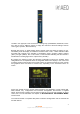
2.1.2.4. Control room monitoring section. Located in the lower right corner of the AEQ FORUM control surface are a two-coloured display, three rotary encoders and four keys. • In the two-coloured OLED display are shown the output levels for the control monitoring signals and the selected sources in each case, for control headset, control speakers and CUE.
o o “Mixer”: each key pressed adds the signal to be monitored to the summing bus. “Exclusive”: each key pressed connects the signal to the summing bus and disconnects any signal previously selected. In case there are no channels sent to CUE, the signal or signals selected in this section will be shown in the lower control VU meter (see section 2.1.2.1 of this manual). 2.1.2.5. Studio room monitoring section.
These four keys can have two working modes that are selected from the Configuration Software (see section 4.2.4 of this manual): o o “Mixer”: each key pressed adds the signal to be monitored to the summing bus. ”Exclusive”: each key pressed connects the signal to the summing bus and disconnects any signal previously selected. 2.1.2.6. Talkback. Talk-back section allows the console operator to communicate directly with the studio and remote guests (lines).
The AEQ FORUM design does not include a fan or mechanical heat sink thus ensuring silent operation, perfect for self-control facilities or applications that require absolute silence. The right side of the vent area integrates the CUE speaker. 2.1.4. Wrist-rest and side trims. The AEQ FORUM has a frame around the sides and bottom of the control surface, forming part of the chassis that houses all the electronics. This framework is transformed into a wrist-rest at the bottom.
2.2. Description of the rear panel and connections. The ease of installation and set-up has been a priority in the design of AEQ FORUM. The equipment is self-contained and can be installed either desktop or countersunk. To connect cough cut, remote control of external devices, ON AIR lights, etc... AEQ FORUM has 8 general purpose inputs (GPI), 8 general purpose outputs (GPO) and another 4 relay outputs.
2.2.1. Power supply. A On the left side of rear FORUM is placed the power supply module which incorporates the DC/DC converters that provides the internal circuitry power of the console. Externally you can see the 48V DC Speak-On connector to which the external 48V DC power supply is connected. The power supply provided is switching and supports between 100 and 240VAC, delivering 160W-3, 34A @ 48 V DC. AEQ FORUM external power supply On request, a redundant 2RU rack-mounted power supply can be delivered.
2.2.2.1. GPIO. AEQ FORUM incorporates several electronic general purpose interfaces (GPIO), either of the opto-coupled or physical contact type and always available on the rear panel of the unit. OPTO-COUPLED GENERAL PURPOSE OUTPUTS OPTO-COUPLED GENERAL PURPOSE INPUTS RELAY CONTACT GENERAL PURPOSE OUTPUTS 2.2.2.1.1. Opto-coupled GPI. The AEQ FORUM includes 8 electronic interface of opto-coupled type GPIs through the two female DB9 connectors in the “GP INPUTS” section.
On request, this wiring kit can be supplied with connectors explicitly specified by the customer. For more information please refer to AEQ sales department or authorised distributors. 2.2.2.1.2. Opto-coupled GPO. The AEQ FORUM includes 8 electronic interface of opto-coupled type GPOs through the two male DB9 connectors in the “GP OUTPUTS” section. One of them houses the GPOs numbered from 1 to 4 and the other one from 5 to 8. Specifications: • • • • • Opto-coupler protected outputs (TLP127).
Electronic associated with physical contact GPO In order to simplify the installation phase, AEQ offers a prefabricated wiring kit specifically for GPO outputs: CAB FR GPR, female DB9 connector soldered to 4 meters of cable open-end termination for GPO. More information in section 2.2.4 of this manual.
The RJ45 pin-out is as follows: Pin 5: White and Blue Pin 4: Blue Pin 6: Green Pin 3: White and Green Pin 7: White and Brown Pin 2: Orange Pin 8: Brown Pin 1: White and Orange 2.2.2.3. Synchronism. AEQ FORUM has an external sync input for AES 11 and TTL formats. The input connector is an RJ45 on the rear panel of the unit identified as “EXT. SYNC”. Pin 1 2 3 4 5 6 7 8 Case EXT.SYNC connector TTL_SYNC_IN TTL_SYNC_IN_GND TTL_SYNC_OUT GND AES_SYNC_OUT+ AES_SYNC_OUTAES_SYNC_IN+ AES_SYNC_INEarth 2.2.
Control / Studio Monitoring outputs (SUB-D male 9 pin): Pin 1 2 3 4 5 6 7 8 9 MONITOR STUDIO connector GND OUT LNot connected GND OUT ROUT L+ Not connected Not connected OUT R+ MONITOR CONTROL connector GND OUT LNot connected GND OUT ROUT L+ Not connected Not connected OUT R+ On request, this wiring kit can be supplied with connectors explicitly specified by the customer. For more information please refer to AEQ sales department or authorised distributors. 2.2.2.5. Control and studio headphones.
2.2.2.7. Optional MADI communications module. On the rear panel of AEQ FORUM you can find the physical connector for the AES10 - MADI interface built into the console. The connector is an SFP chassis (Small Form-Factor Pluggable - SFP) where you allocate the optional fiber-optic transceiver. MADI protocol, which stands for multichannel audio digital interface is a professional standard of data transmission for digital audio signals over 56 channels on a single cable.
Using the modules described above, in the numbers and available free position of the 14 available slots on the rear panel of AEQ FORUM, each customer can customize their AEQ FORUM mixing console to exactly fit its specific requirements and applications. In order to simplify the installation phase, AEQ offers a prefabricated wiring kits for the different audio inputs and outputs modules available. More information in section 2.2.4 of this manual. 2.2.3.1. FR02 Digital inputs/outputs module.
By changing some jumpers on the FR02 module you can work with digital signals in SPDIF format.
NOTE 2: only when the FR03 module edition is previous to edition 4 and the firmware version of the CPU module of BASE PBA is previous to 1.44, in case you use a microphone that needs Phantom power it’s important that you activate that option only when the microphone is already connected to the corresponding input, in order to avoid unconfigure the gain of the rest of the microphones (anyway it’s possible to recover those gains configuration just by refreshing the gain of at least one microphone per module).
2.2.3.4. FR05 Analogue line outputs module. The AEQ FORUM FR05 module incorporates 8 electronically balanced monophonic line level outputs and are available physically through two DB15 male connectors identified as “ANALOG OUTPUTS 1 To 4” (upper), and “ANALOG OUTPUTS 5 To 8” (lower).
2.2.3.5. FR14 AoIP module. The AEQ FORUM FR14 AoIP module is installed as any other input/output module on the rear panel of the console and gives you up to 32 input audio channels and up to 32 output audio channels. The module has 2 Ethernet connectors identified as “LAN 1” (main interface) and “LAN 2” (secondary interface), both with its corresponding signalling LEDs. Those LEDs indicate the status of audio local network connection: - Off: no local network connection.
When you connect a USB module to a PC through any of the USB ports, the PC will automatically recognize it as a new audio device (it will be shown as “USB Audio CODEC”). To this device you can send audio from any audio playback application in the same way as if it was an external professional audio board. It is also possible to record any audio from the mixing console in the computer by using any recording application.
2.2.4. Wiring. All wiring kits described below are optional and have been designed by AEQ to simplify the installation of the unit. To facilitate the quick connection of the console in almost any installation, AEQ can supply audio and data cables with the corresponding DB-type connectors that are used to connect the unit.
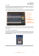
3. DESCRIPTION OF THE INTERNAL MENU. The AEQ FORUM internal menu is displayed on the main screen of the Control and Monitoring section of the control surface. Most of them allow you to modify the values shown (although some screens of the internal menu are merely informative), changing routing, gains or applying processes to the audio signals. For this purpose, the three rotary encoders and the four contextual keys associated to this screen will be used.
The four options visible on the last line of the display are associated with the four contextual keys below, from left to right: • • “BACK”: returns to the previous menu screen. “SET”: enables you to access to the date and time configuration menu.
• “CHRONO”: enables you to configure and activate the chronometer option. The format on screen is HOURS:MINUTES:SECONDS. The “START” contextual key initiates the chronometer, the “STOP” key (the same key that changes its function) stops it, and the “RESET” key re-establishes the initial zero value (even when the chronometer is launched). The “BACK” key allows you to return to the previous screen (it also stops the chronometer and re-establishes the initial zero value). 3.2. “LOGIN/LOGOUT“ menu.
The “LOGIN”/“LOGOU” contextual key has two possible uses: LOGIN to register yourself (depending on the password used you will access to a certaind level) and LOGOUT to deregister (this way you gain access to level 0). When you register through the option “LOGIN”, the “PASSWORD” screen appears: six spaces are displayed on screen associated with the six digits (as maximum) of the password. The password must be configured previously from the configuration software (see section “4.
3.3. “MEMORY“ menu. This menu enables you to manage the configuration memories as snapshots. In two consecutive screens, the 7 memory positions available for user-defined configurations are shown.
• • “SETUP”: which displays and allows you to change the IP configuration associated with the two Ethernet ports available on the rear panel of the equipment (“LAN” and “ETHERNET”: see section 2.2.2.2 of this manual) in the form of IP address (IP1 or IP2), subnet mask (MASK) and gateway (GWAY). Only level 3 users can modify these parameters (the “SETUP” key is shown to other users but is not active). “SELECT”: advanced configuration of audio inputs/outputs, internal routing and processes. 3.4.1.
• “STATUS”: allows you to access to the information regarding the routing and process DSPs percentage of use. In case the working limit of any of them is exceeded the indication “OVL” (Overload) is shown. 3.4.2. “SETUP“ menu. Through the “IPSET” option in a contextual key, this menu enables you to display and modify the IP configuration associated with the two Ethernet ports available on the back panel of the equipment (“LAN” and “ETHERNET”: see section 2.2.2.
LAN ETHERNET 3.4.3. “SELECT “ menu. This menu enables you to perform advanced configuration operations on audio inputs/outputs, processes and internal routing of all of the signals present in the console. The options available through the contextual keys below the screen, from left to right, are: • • • “BACK”: pressing this key allows you to return to the previous menu screen. “INPUT”: configuration of input audio signals, as well as processes and routing associated with those signals.
• Name of the channel, in alphanumeric format containing up to 6 characters. This is the same identifier as the one shown in the channel display. See section “2.1.1.3. Channel display” in this manual. • Hardware corresponding to the audio input of this channel, in format HW: xx.yy, where xx is the number of the slot where this inputs/outputs module is installed, and yy is the audio channel of this inputs/outputs module.
3.4.3.1.1. Dynamics menu: Compressor/Limiter and Noise Gate. COMPRESSOR / LIMITER: Pressing the “DYNAM” contextual key from the advanced information menu of an audio input channel will give you access to the menu to configure the Compressor/Limiter. Dynamics processors are used to modify the dynamic ranges of an audio signal to adapt it to specific needs or to produce certain sound effects. A compressor enables you to reduce the dynamic range of the signal.
A cursor blinks over the fields placed on the left or on the right to indicate the fields that can be modified at that momento. To change from the one to another just press any of the three associated encoders.
When establishing the settings, the threshold for the noise gate will be much lower than in the case of the compressor, as its operation is the opposite. The noise gate prevents the passing of lower levels of the signal that could be considered noise. Therefore, the range of settings is different. In addition, there is an additional parameter for noise gates, which is “Hold Time.
• “LPF”: allows you to activate the configured low pass filter (the associated LED will light). Pressing this contextual key for three seconds opens the cut-off frequency configuration menu: this configuration is accomplished by turning the first associated encoder and pressing the “BACK” contextual key to return to the previous screen once this parameter is configured (between 1000 and 20000Hz).
• • • • • • Name of the channel, in alphanumeric format containing up to 6 characters. This is the same identifier as the one shown in the channel display. See section “2.1.1.3. Channel display” in this manual. Hardware corresponding to the audio input of this channel, in format HW: xx.yy, where xx is the number of the slot where this inputs/outputs module is installed, and yy is the audio channel of this inputs/outputs module.
The operation of the contextual keys, from left to right, is as follows: • • • • “BACK”: pressing this key allows you to return to the previous menu screen (the changes you may have made are saved). “ADD”: enables you to create the cross-point toward the output signal or bus that is highlighted at that moment. “DEL”: enables you to delete the cross-point toward the output signal or bus that is highlighted at that moment.
• • • • • Name of the channel, in alphanumeric format containing up to 6 characters. Hardware corresponding to the audio output of this channel, in format HW: xx.yy, where xx is the number of the slot where this inputs/outputs module is installed, and yy is the audio channel of this inputs/outputs module. In stereo channels, yy represents the audio channel corresponding to the left channel of the stereo pair. The right channel corresponds to the number just above.
4. CONFIGURATION SOFTWARE. The AEQ FORUM console is ready for use once the mixer inputs and outputs have been properly connected. The console is shipped with the Audio inputs/outputs modules as requested by each customer. However, the name tags used for the channel audio inputs and outputs are generic (MIC 1, ANA 3, DIG 5 ...) and routing and effects programmed are AEQ standards that are used for functional testing of the console, whereas these settings may not be entirely to the preferences of the client.
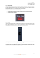
Once the “Forum Setup” application is installed (by default, in C:\Program files \ForumSetup), you can start it up by double-clicking the icon displayed on the desktop: The configuration program will also be accesible from the Start menu. When the application starts up, the access screen will appear asking user to introduce name and password. Only the users defined as administrators (“Administrator” access level) can access to this application.
This initial screen shows information regarding the software version and the current user logged into the application. On the left side of the screen all the relevant menus and submenus are available. These are drop-down menus and are activated by clicking on the desired option. The list of available menus is: • • • • “Administration”: manage from here the equipment operational levels, authorised users of the mixing console and the communication between the remote configuration software and the mixer.
4.1. “Administration” menu. This menu allows you to manage levels of users that can operate the mixer and control the communication between the remote configuration software and the mixer. Clicking on the “Administration” section of the main screen the complete list of submenus is shown: • • • “Configurations”: allows you to manage the configuration exchange between the software application and the AEQ FORUM.
There are two distinct areas in this submenu: • “Offline Operations”: allows you to execute actions where it is not necessary that the Forum Setup application is in direct communication with the AEQ FORUM mixer. There actions are available: o “Import”: allows you to load in the application complete conifigurations previously stored in a source file. By clicking the “Import” button, a standard Windows “browse for file” window will open to locate the file to import.
The associated buttons functions are the following ones: o “Read”: allows you to read the configuration currently active in the AEQ FORUM mixer and download it in the Forum Setup application. IMPORTANT NOTE: the active configuration at that moment in the application is overwrited and get lost (unless you previously save it by means of “Export” option).
for the “Forum Virtual” application (available in future software versions): or for the “Forum Screen” application (available in future software versions): The “Unlock” button allows you to confirm the key and, when it’s correct, activate the function. In case the key is not the right one, an error message will appear: IMPORTANT NOTE: MADI functionality is not compatible with AoIP (audio over IP) functionality, both options can’t be active at the same time.
4.1.2. “User Configuration” submenu. “User Configuration” submenu is accessed, from the drop-down menu “Administration”, by clicking on the icon: “User Configuration” submenu allows you to set access levels and create users to operate the AEQ FORUM mixing Console. The display in this submenu shows the list of registered users and their associated parameters: • • • “User”: alphanumeric name of the user. The maximum number of digits is limited to 32.
The lower part of the “User Configuration submenu includes a set of standardized buttons to manage the list of registered users: Allows you to scroll to the top of the list. Allows you to move to the position immediately above in the list. Allows you to move to the position immediately below in the list. Allows you to scroll to the last position of the list. Allows you to insert a new entry in the list. Allows you to delete the selected entry from the list. Confirmation is requested.
4.1.3. “About Forum Setup “ submenu. “About Forum Setup” submenu is accessed, from the drop-down menu “Administration”, by licking on the icon: “About Forum Setup” submenu simply shows information regarding the software version and the current user logged into the application. 4.2. “Hardware Configuration“ menu. This menu allows you to configure the system inputs and outputs modules as well as the logical audio channels created from the physical inputs and outputs.
IMPORTANTE NOTE: In order to access to any of these submenus, it’s neccesary to have a configuration loaded in the application (in case there’s no configuration, the message “Empty configuration. Please read configuration before use” is displayed). Therefore, you have to either connect to AEQ FORUM console and read its configuration or load a configuration by means of “Import” option (see section 4.1.1 of this manual; you can find the “DemoConfiguration.FSC” file in C:\Program files \ForumSetup\Demos). 4.2.
• “Get Hardware Info”: allows you to load automatically in the application the configuration of hardware modules integrated into the console. By clicking on this option, the ForumSetup software communicates with the AEQ FORUM mixing console (therefore, there should be connection between the computer where is running the configuration software and one of the network ports of the mixing console) and retrieves the hardware configuration as installed in your system.
o FR04 - Analog Audio Inputs Card. o FR05 - Analog Audio Outputs Card. o FR14 - AOIP Audio I/O Card. IMPORTANT NOTE: AEQ FORUM supports up to two FR14 modules per console and these can be installed only in slots 13 and 14 (when there is only one module, it will be placed in slot 14). When you try to configure it in another slot an error message appears. o FR22 - USB Audio I/O Card. o FR33 - Hybrid Audio Card.
• AOIP: FR14 AoIP modules are installed as any other input/output module on the rear panel of the console and give you up to 32 input audio channels and up to 32 output audio channels per module. The maximum number of FR14 modules present in any AEQ FORUM console is 2. The configuration options are: o o o “Disabled/32 Channels/64 Channels”: allows you to deactivate this option or select between 32 o 64 channels (depending on how many FR14 modules will be installed: one or two).
• • Edit the "Label" to identify the assigned role. Configure the working mode (“Level” column) of each GPI. The options are: o o o o “High”: GPI activated on high level. “Low”: GPI activated on low level. “On Change”: GPI activated by transitions from high to low or the inverse. “TH02”: GPI to accept the particular signalling that is generated by the AEQ TH-02EX MkII digital hybrid, as well as to enable the remote control of this particular equipment. 3. GPO: General Purpose Outputs.
4. RELAY: allows you to configure the GPO outputs on physical contact relays as opposed to the opto-coupled GPO's on open collector transistors. There are four contact relays or contacts. The advanced configuration menu of GPOs is accessed by clicking “Click to [CONFIG]” and then clicking again on the “CONFIG” button that will appear. This configuration menu is exactly like the previously detailed for GPOs. 4.2.2. “Mixer Bus Configuration” submenu.
• • • • • • • • • “Control“: output bus toward control monitors and headphones, stereo and with working mode defined as “Control”. “MPX 1“: mono and with working mode defined as “MPX 1”. “MPX 2“: mono and with working mode defined as “MPX 2”. “MPX 3“: mono and with working mode defined as “MPX 3”. “MPX 4“: mono and with working mode defined as “MPX 4”. “MPX 5“: mono and with working mode defined as “MPX 5”. “MPX 6“: mono and with working mode defined as “MPX 6”.
• • • “Label”: name of the bus. Maximum number of characters recommended is 6. “Working Mode”: is the description provided by the system regarding the functionality of each bus: Program, Audition, Aux 1, Aux 2, Cue, Studio, Control, MPX 1 to 8 or Internal. “Stereo”: allows you to configure the bus as a mono or stereo one. The lower part of the “Mixer Bus Configuration” submenu includes a set of standardized buttons to manage the list of internal buses: Allows you to scroll to the top of the list.
• • • “Label”: alphanumeric name of the channel. Maximum number of characters recommended is 6. This is the name that appears in all displays and menus of the AEQ FORUM control surface. “Model”: type of the physical inputs/outputs module present in the rear panel of the unit. This field will be populated automatically once the “Board Configuration” has been accomplished (see section 4.2.1.1 of this manual). “Config”: access to advanced settings menu for the selected logical channel.
• “Remote ON/OFF”: allows you to select a GPI (from the list defined in chapter 4.2.1.2) to perform the remote start function for this channel (Channel ON/OFF keys on control surface: see paragraph 2.1.1.8 of this manual). “None” indicates there is no Remote ON/OFF function associated to that channel. • “Solo”: allows you to select a GPI (from the list defined in chapter 4.2.1.
• • • • • • • “Cough Cut”: allows you to select a GPI (from the list defined in chapter 4.2.1.2) to perform the cough-cut function for this channel. This option is only available for microphone channels. “None” indicates there is no cough-cut function associated to that channel. “Remote PFL”: allows you to select a GPI (from the list defined in chapter 4.2.1.2) associated with the sending of the input channel to the CUE bus. This option is only available for microphone channels.
• • • “Label”: alphanumeric name of the channel. Maximum number of characters recommended is 6. This is the name that appears on all displays and menus of the AEQ FORUM control surface. “Default Routing”: allows you to configure the signal routed by default to that output channel. You can select any input channel (“Inputs” in “Type” column) or any of the internal summing buses (“Mixer” in “Type” column; see section 4.2.2 of this manual).
There are two distinct parts in this submenu: the upper part is dedicated to the configuration of the Studio Room section and the lower to the Control Room section. 4.2.4.1. “Studio Room Section“. This section of “Monitoring Configuration” submenu lets you choose how the four keys under the display of the Studio Room Control and Monitoring section shall work, either in “Mixer” or “Exclusive”.
In this section you can also allocate the GPO physical outputs associated with Control “OFF AIR” green light (indicates that there are no sources, typically microphones, activated in the control room) and “ON AIR” red light (indicates that there are no sources, typically microphones, activated in the control room). You can choose between the opto-coupled GPO´s (1 to 8) or the contact relay GPO´s (9 to 12): these last ones are recommended. See section 2.2.2.1 of this manual. 4.2.5.
4.3. “Programmable Configuration” menu. This menu allows you to configure the internal routing of audio signals and the functions associated with the programmable keys, as well as define mics groups, create processes presets and manage the configuration memories (snapshots) of the unit.
The bottom of the workspace in this submenu contains two options: • “Delete Routing”: eliminates the selected cross-point. Confirmation is requested. • “Insert Routing”: you can create a cross-point through a simple process that allows you to select an input channel or an internal summing bus as the source, and an output channel or an internal summing bus as the destination. These names or labels have been previously defined in the “I/O Configuration” submenu.
4.3.2. “Programmable Keys” submenu. “Programmable Keys” submenu is accessed, from the drop-down menu “Programmable Configuration”, by clicking on the icon: “Programmable Keys” submenu lets you configure the actions associated with each of the 15 programmable keys found in the Control and Monitoring section of the AEQ FORUM control surface (please refer to Section 2.1.2.2 of this manual).
To set a programmable key, simply click on it with the mouse and select from the list on the right to associate action. The available options are: • • • • • • • • “None”: no action associated. “General”: associated with activation of GPI and/or GPO. “Salvo”: allows you to configure activation/deactivation of a Salvo. “Codec”: associated with remote control of external communications equipment through GPIs and GPOs.
• • • • • • • • “Group”: allows you to assign the programmable key to a group. Assign a key to a group when you need to define exclusive operation between various programmable keys (the activation of one of them entail the deactivation of the one active at that moment). You can create up to 8 programmable keys groups. “None” indicates that key is not assigned to a group. “Latch Mode”: allows you to configure the key as “Latch” or “Non Latch”, so after you press it, the key stays fixed or not.
The lower part of the “Programmable Keys” submenu will allow you to configure the Salvo content. There are two tabs: “General” y “Salvo”. The “General” tab gives you access to a screen identical to the one described in the previous section and allows you to configure the operational sequence of the programmable key and its relationship with the system GPI´s and GPO´s.
• • “Modify": allows you to modify a preconfigured action. The options on this screen are identical to those described for “Inser” option. “Delete”: allows you to delete a preconfigured action. Confirmation is requested. 4.3.2.4. Configuration of “Codec” programmable keys. Programmable keys that are set to “Codec” enables you to assign functions associated with remote control of external communications equipment (such as audio-codecs) through associated GPIs and GPOs.
• • • • • • • • • “Ring”: the key starts to blink when there is an incoming call. This function can be combined in the same key with any of the following three functions. “Extended”: enables the option of frequency extender for the FR33 telephone hybrid. The key turns on when activated. “Wait”: allows you to put the call on hold (you can send audio to the telephone line, but the audio from the line is not received in the console). The key turns on when activated.
For Eagle audio-codec, the available options are: • • • • • • • • “Ring”: allows you to select the GPI where the incoming call signal provided by the codec is wired. The key starts to blink when there is an incoming call. This function can be combined in the same key with any of the following four functions. “Wait GPI”: selects and configures the physical GPI input associated to “WAIT” function. The key turns on when WAIT mode (call on hold) is activated manually in the audio-codec.
2 3 4 For Phoenix Studio or Stratos audio-codec, the available options are: 82 AEQ FORUM Digital audio mixer for broadcast applications
• • • • • • “Ring”: allows you to select the GPI where the incoming call signal provided by the codec is wired. The key starts to blink when there is an incoming call. This function can be combined in the same key with any of the following four functions. “Call GPO”: selects and configures the physical GPO output associated to “CALL” function. The key turns on when activated and makes the call from the corresponding channel.
4.3.2.6. Configuration of “Cue Reset” programmable key. “Cue Reset” option allows you to configure a programmable key as a key to disconnect immediately all the signal sendings to the CUE bus at that moment. A key set to this function is assigned with a dedicated icon. The lower part of the “Programmable Keys” submenu will show no options when this configuration mode is selected.
4.3.2.8. Configuration of “Memory” programmable keys. Programmable keys that are set to “Memory” allows you to load the selected configuration memory or snapshot. A key set to this function is assigned with a dedicated icon. The lower part of the “Programmable Keys” submenu will allow you to configure the memory or snapshot associated to the programmable key.
4.3.3. “Mic Group Configuration” submenu. “Mic Group Configuration” submenu is accessed, from the drop-down menu “Programmable Configuration”, by clicking on the icon: “Mic Group Configuration” submenu allows you to define groups of microphones. Within this submenu there are two distinct areas on the screen: • • The left side shows the list of groups of microphones set up.
o “Label”: name or ID for the group of microphones. A maximum of 6 characters is recommended. o adds ALL microphones or audio inputs from the “Inputs availables” column to the “Inputs in the Group” column. o adds ONLY the microphone or audio input selected from the “Inputs availables” column to the “Inputs in the Group” column. o removes ONLY the microphone or audio input selected from the “Inputs in the Group” column back to the “Inputs availables” column.
“Preset Configuration” submenu allows you to create default settings associated with the different audio processes available in AEQ FORUM: equalizers, filters, compressors/limiters and noise gates. The main screen of this submenu is presented as a list of all the pre-sets created ordered by their “Id” and with a “Label” or name as identifier.
The main screen of this submenu has also two buttons at the bottom: • • “Import Presets”: allows you to import to Forum Setup application all pre-sets stored on an AEQ FORUM mixing console that is connected through IP to the computer where the application is installed. “Export Presets”: allows you to export from Forum Setup application all stored pre-sets to an AEQ FORUM mixing console that is connected through IP to the computer where the application is installed.
Dynamics processors are used to modify the dynamic ranges of an audio signal to adapt it to specific needs or to produce certain sound effects. A compressor enables you to reduce the dynamic range of the signal. Your purpose may be to adapt a signal with a very broad dynamic range to a circuit that will not support such wide variations in level, or to generate a certain sound in a signal. The graph represents the variation produced in the different levels of the signal applied to this function.
• • • “GAIN“: this enables you to apply a general gain to the signal. This entails a general increase of the signal level, which will be especially noted at low input levels that are under the threshold set. It ranges between 0 and 40dB. “OK”: allows you to accept the created or edited configuration. A double confirmation is required. “Cancel”: allows you to reject the created or edited configuration. No change you may have made is saved. 4.3.4.2. Advanced configuration of Noise Gate.
The threshold must be adjusted to a level slightly higher than the level of the noise to be avoided. Thus, the threshold will be set at a very low level. Above the threshold, the noise gate does not act (unity gain), letting the rest of the signal through without processing it. The gate remains closed; i.e. when the signal surpasses the threshold level, the gate opens.
4.3.4.5. Advanced configuration of High Pass Filter. From the initial screen of the pre-sets advanced information menu (“Digital Sound Processes”) you can configure and activate/deactivate the High Pass Filter operation. When you select the “Active” checkbox, the “Configure” button gets active and gives you access to the graphic display where the High Pass Filter associated parameters can be modified.
4.3.5. “SnapShot Configuration” submenu. “SnapShot Configuration” submenu is accessed, from the drop-down menu “Programmable Configuration”, by clicking on the icon: “SnapShot Configuration” submenu allows you to manage the different configurations memories stored in AEQ FORUM and available to operators through the internal menu of the main screen of the Control and Monitoring section of the unit (please refer to section 3.3 of this manual).
The available options in the snapshots advanced configuration menu, described from left to right and top to bottom, are: • • • • “Label”: alphanumeric label for the snapshot memory. “Faders”: 20 drop-down menus allow you to assign an input audio channel to each one of the physical faders of the control surface (up to 12 for AEQ FORUM and up to 20 for AEQ GRAND FORUM). The faders are numbered, from left to right, 1 through 20.
• • • • “Control”: section where you can configure the initial activation of one or several keys to send signal to monitor and headphones placed under the display of the control monitoring section. The available options are “Program”, “Audition”, “Cue” and “Sel” (when section is configured in “Exclusive” mode, you can activate only one key: see section 4.2.4.1 of this manual).
From left to right and from top to bottom the available options are: • • • • • • • • • • • Name of the snapshot (test 1 in the example). Name of the channel (ANA 3 in the example). “Routing”: allows you to configure the initial activation (or not) of the quick routing keys that are available above each fader channel of AEQ FORUM control surface. “Balance/Panorama”: allows you to manage the initial balance or panoramic control for this input channel.
From left to right and from top to bottom the available options are: • • • • • Name of the snapshot (test 1 in the example). Name of the channel (dig 2 in the example). “Digital Gain”: allows you to control the output gain of the selected channel from -12dB to +12 dB, by means of a graphical representation of a sliding fader. “OK”: allows you to accept the created or edited configuration. “Cancel”: allows you to reject the created or edited configuration. No change you may have made is saved.
4.4. “Firmware Upgrade” menu. This menu allows you to update the firmware versions for the AEQ FORUM, allowing for the implementation of new features and developments in future versions.
Selecting any of the modules, the associated firmware information will be shown.
The procedure to upgrade a module firmware is as follows: 1. Place the pointer on the module to be upgraded, press the right mouse button and then the “Upgrade” option that appears. 2. In the new window that appears, press the button and select the “AFU” upgrading file (AEQ Firmware Upgrade) that contains the new version you want to load. In case you select an AFU file that does not correspond to the selected module, an error message will be displays: 3.
4. From this point on, the application changes automatically to “Upgrade View” screen in order to show you the upgrading progress. See section 4.4.2 of this manual. IMPORTANT NOTE: You should not act on the system and you must never turn off the equipment during the upgrading process, since this action may deprogram the module that you are trying to upgrade. The firmware upgrade right order is: FRCH module/s, MSC module and BASE PBA (FPGA, DSP Process, DSP Router and CPU).
o o o o o o “Slot”: identifies the physical location of the module to be upgraded. In the case of a module placed at the rear panel of the AEQ FORUM, the slot where it is placed will be shown (S13 for instance). In case of a FRCH 4 faders module, its position will be shown (F01, F02 or F03). In case of a base board module, MB (Mother Board) indication will be shown. “Card”: shows the type of the functional module that is subject to the firmware upgrade.
5. A.E.Q. GUARANTEE. AEQ warrants that this product has been designed and manufactured under a certified Quality Assurance System. AEQ therefore warrants that the necessary test protocols to assure the proper operation and the specified technical characteristics of the product have been followed and accomplished. This includes that the general protocols for design and production and the particular ones for this product are conveniently documented. 1.
6. ADDITIONAL INFORMATION. NOTE: This equipment complies with the limits for a Class A digital device, pursuant to part 15 of the FCC Rules. These limits are designed to provide reasonable protection against harmful interference when the equipment is operated in a commercial environment. This equipment generates, uses, and can radiate radio frequency energy and, if not installed and used in accordance with the instruction manual, may cause harmful interference to radio communications.