
User Manual


12
21
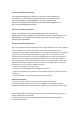
Note: The above physical connection diagram is for
3-Wire system, the below diagram would be for the
2-Wire system.
In 2-Wire system, since the power input terminals
of Nano Dimmer just need to connect one power
wire, so the terminal of “N” on Nano Dimmer should
connect to the “L” on the Nano Dimmer.
S1 S2
N
L
OUT
COM
N
L
Mounting the gang box.4.
Position all wires to provide room for the device.
Place the Nano Dimmer inside the gang box
towards the back of the box.
Position the antenna towards the back of the
a.
b.
Security or Non-security feature of your Nano
Dimmer in Z-Wave network.
Including Nano Dimmer as a non-secure device:
If you want your Nano Dimmer as a non-secure
device in your Z-Wave network, press the Action
Button once on Nano Dimmer when you pair it to
your gateway. If inclusion is successful, the green
LED will be on for 2 seconds, and then return to a
solid indication. If inclusion is unsuccessful, the red
LED will be on for 2 seconds and then return to a
colourful gradient.
Including Nano Dimmer as a secure device:
In order to take full advantage of the Nano Dimmer,
you will want your Nano Dimmer as a security device
that uses encrypted messages to communicate in
your Z-wave network. A security enabled controller/
gateway (or Z-Wave Plus controller) is required.
operation manual for these control points for specic
instructions on monitoring the Nano Dimmer.
Set your Z-Wave Plus controller into pairing1.