
User Manual

15
4.3. CONNECTING PROBES, SENSORS, TRANSMITTERS, OR SIGNAL CONDITIONERS
The L452 Data Logger operates with a great variety of probes having outputs of the following type:
Voltage: ± 100 mV, ± 1 V or ± 10 V
Current: 4 - 20 mA
Pulse: ± 10 V
On/Off (discrete): ± 10 V
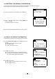
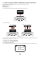
Place the connecting strip provided on the terminal block of the instrument and push it home.
V
INPUT 1
INPUT 2
VmA mA
30V
MAX
L452
SIMPLE LOGGER III
Figure 8
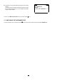
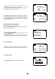
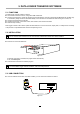
Then connect the probes.
V
INPUT 1
INPUT 2
VmA mA
30V
MAX
V
INPUT 1
INPUT 2
VmA mA
30V
MAX
Channel 1
Channel 1
Figure 9
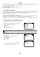
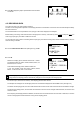
Use a small at blade screwdriver to unscrew the screws of the terminal block. Insert the wires, then screw the screws back in so
that the wires cannot be pulled out of the connector.
4.4. DISPLAY OF THE MEASUREMENTS
4.4.1. CURRENT OR VOLTAGE INPUTS
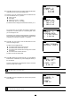
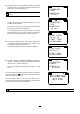
Once the probes have been connected, switch the instrument on. The display unit indicates the values on the measurement inputs.
1
2
m3/s
mmHg
2.53
9.75
4-20mA current probe Voltage, pulse, or discrete probe.
Channel 2
Channel 2
Figure 10