
User Manual

14
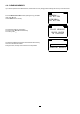
SCALE LOW:
0.0 mV
= 0.0 mV
CHANNEL 1:
SCALE HIGH:
100.0 mV
= 100.0 mV
CHANNEL 1:
EQUIVALENCE:
1.00 Pulse
= 1.00 Wh
CHANNEL 1:
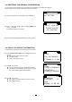
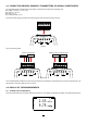
Press . The next 2 screens are used to dene transformation
coefcients for the current and voltage inputs.
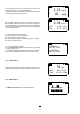
For example, if you use a temperature sensor that delivers 4mA
at -10°C and 20mA at 100° C, you enter:
Input: 4-20 mA
Unit: degC
Scale Low: 4.0 mA = -10 degC
Scale High: 20.0 mA = 100 degC
The instrument then displays the measurement directly in °C.
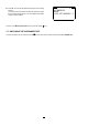
For a pulse input, you can dene the number of pulses that
corresponds to a certain power, or to something else, since
you can change the unit.
For example, if you count the number of teeth on a toothed ring
and know that one revolution corresponds to 14 teeth (hence
14 pulses), you can enter "14 pulses = 1 revolution".
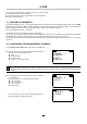
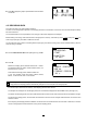
Press . The next screen is used to dene alarms for the
current and voltage inputs.
The alarm can be triggered when:
the measurement is above the high limit,
the measurement is below the low limit,
the measurement is either above the high limit or below
the low limit,
the measurement is within the limits.
The alarm can also be deactivated.
ALARM TRIGGER:
OUTSIDE LIMITS
UPPER LIMIT:
0.00 mV
LOWER LIMIT:
0.00 mV
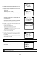
Press to dene the high and low limits. If you have dened
transformation coefcients, they will be displayed directly in
the unit dened.
To return to the example of the temperature sensor, the limits
will be 100 degC and -10 degC.
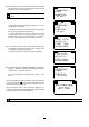
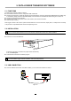
Press to go to the conguration of channel 2 and proceed
as for channel 1.
±100 mV
CHANNEL 2:
ENABLED
INPUT:
Both measurement channels must have the same type of input. If you set input 2 to pulse and input 1 was voltage, channel
1 automatically changes to pulse.
The upper limit must be greater than the lower limit. If you program a lower limit that is above the upper limit, the instrument
sets both limits to the same value.