Equipped with AEM ® Dryflow™ Filter No Oil Required! INSTALLATION INSTRUCTIONS PART NUMBER 21-8128DC (Gun Metal Gray Finish) 2015-16 FORD F150 2.7L & 3.5L V6 Turbo 2017-18 FORD F150 2.7L V6 TURBO 1 C.A.R.B. E.O.
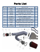
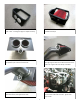
Parts List ITEM NO. PART NUMBER DESCRIPTION QTY. 1 9448 1/2" BNDHOSE CLAMP,2.56"-3.50" 5 2 5-300 HOSE; SILICONE 3.00 X 3" BLK 1 3 2-1532C INTAKE TUBE; ASSY, 3.00"OD X 40" 1 4 784646 GROMMET, 1/2" 3/32 GW 1 5 102499 EDGE TRIM; 3/4"BULB,TOP LOC.,42"L 1 6 1228599 MOUNT, RUBBER 1" X 6MM 1 7 444.460.04 NUT; M6 HEX SERRATED 2 8 08275 WASHER; 1/4"ID X 5/8"OD - SAE 2 9 20-8551 HEAT SHIELD, AEM-21-8128, FORD F150 1 10 5-430 HOSE, ADAPTER 4.00/3.
Read and understand these instructions BEFORE attempting to install this product. Failure to follow installation instructions and not using the provided hardware may damage the intake tube, throttle body and engine. If you need any assistance please call1-800-858-3333 to speak with a representative in our Customer Service Center before returning the product. Tools Needed: 1. Preparing Vehicle a. Make sure vehicle is parked on level surface. b. Set the parking brake. c.
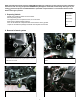
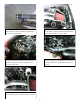
e. Remove the stock air intake system from the vehicle. Note: Do not discard any of your stock equipment. f. Remove your stock air filter from the lower air box. g. Remove the air intake temperature sensor from the stock intake tube. Note: This will be reused in step 3b. h. Remove the O-ring from air temperature sensor. Note: The O-ring will not be reused. 3. Installation of AEM® intake system. a.
c. Install the provided edge trim onto the heat shield as shown. Note: Trimming the edge trim maybe necessary. d. Install the AEM filter into the heat shield with the provided hose clamps. e. With the provided hardware, install the rubber mount/washer/nut onto the heat shield tab. f. Install the AEM intake tube into the AEM air filter while aligning the rubber mount with the bracket on the intake tube. Tighten the hose clamps on the filter. g.
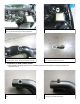
i. Install the straight coupler with hose clamps onto the AEM tube. Note: Use soap and water to allow the coupler to slide on the intake tube. j. Install the assembled AEM intake tube and heat shield into the vehicle. Align the heat shield into the lower air box and latch the clips to secure it in place. k. Align the AEM intake tube with the step coupler that was previously installed in step 3h. Tighten the hose clamp circled at this time. l.
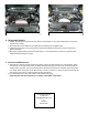
AEM INTAKE INSTALLED STOCK INTAKE INSTALLED 4. Reassemble Vehicle a. Position the inlet pipes for the best fitment. Be sure that the pipes or any other components do not contact any part of the vehicle. b. Check for proper hood clearance. Re-adjust pipes if necessary and re-tighten them. c. Inspect the engine bay for any loose tools and check that all fasteners that were moved or removed are properly tightened. d. Reconnect negative battery terminal and start engine. Let the vehicle idle for 3 minutes.
AEM Air Intake System Warranty Policy AEM® warrants that its intake systems will last for the life of your vehicle. AEM ® will not honor this warranty due to mechanical damage (i.e. improper installation or fitment), damage from misuse, accidents or flying debris. AEM ® will not warrant its powder coating if the finish has been cleaned with a hydrocarbon-based solvent. The powder coating should only be cleaned with a mild soap and water solution.