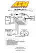
Part Number 30-5143 E85 Analog Wideband Air/Fuel Ratio Gauge Figure 1. Wiring Schematic AEM Gauge-Type UEGO Controller Parts 1 x 35-5143(B/W) E85 UEGO Gauge Assembly 1 x 30-2001 UEGO Sensor 1 x 35-8535 Install Kit (O2 Bung with 6 Butt Connectors) 1 x 10-5143 Installation Instructions 1 x 35-3411 8-Pin Power Harness 1 x 35-3400 6-Pin Sensor Harness 1 x 35-8529S Silver Bezel AEM Performance Electronics 2205 126th Street Unit A, Hawthorne, CA. 90250 Phone: (310) 484-2322 Fax: (310) 484-0152 http://www.
INSTALLATION 1. Disconnect the negative battery cable. 2. Secure the gauge in a 2 1/16th” (52MM) mounting hole with the supplied bracket. 3. Plug the 8-wire power harness into the mating connector on the back of the gauge and connect the wires as shown in Figure 1. Note: the locating tabs on the side of the connector should be nearest the center of the gauge. 4. Mount the sensor as shown in figure 2. 5. Connect the sensor to the gauge using the 6-wire sensor cable.
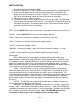
Sensor Mounting A weld-in M18 X 1.5 boss is supplied for sensor installation. Mount the O2 sensor in the exhaust system at least 18 inches downstream from the exhaust port. If you anticipate high EGT's (over 800C), run a turbocharger, run at high RPM for extended periods of time or plan on running leaded race fuel then you must mount the sensor at least 36 inches or more downstream of the exhaust port as all of these can cause the sensor to overheat.
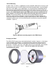
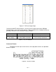
Backlighting The Analog Wideband UEGO Gauge has 7 different backlight colors available to the end user, which closely match some of the more common factory dash panels: white, blue, green, red, orange, light blue, and aqua. To change the backlight color, rotate the backlighting switch using a small precision style screwdriver. The backlight switch is accessed through the small hole in the back of the gauge. ACCESS PORT Figure 4.
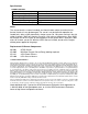
# of Flashes 1-6 Fault Sensor Wiring and/or sensor 7 System voltage below 10 volts dc Corrective Action Check sensor cable for broken wires/shorts Check electrical system for good connections and proper function Table 1. Error Codes Analog Output The analog output from the AEM E85 Analog Wideband Air/Fuel Ratio gauge is a linear dc voltage signal that varies from 0.5 Vdc at 5.6:1 AFR E85 to 4.5Vdc at 11.9:1 AFR E85 over the operating range of the gauge.
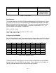
AEM EMS P/N 30-1000/1001/1002/1040/1042 30-1010/1012/1050/1052 30-1020/1060 30-1030/1031/1070 30-1080 30-1081 30-1100/1101 30-1110 30-1120/1121/1130 30-1220 30-1300 30-1310/1311/1312/1313 30-1320 30-1400 30-1401 30-1510 30-1600/1601/1602/1603 30-1610/1611/1612 30-1620/1621/1622/1623 30-1710 30-1720 30-1800 30-1810 30-1820/1821 Lambda #1 Pin D14 C16 D7 C13 C16 C16 B47 1C B6 30 4 76 71 29 44 C2-31 19 46 29 2N C3 C3 D19 A26 Lambda #2 Pin D16 A23 D14 C14 C8 B11 B48 9C B14 31 66 75 73 43 43 C2-33 NA 52 55 4J D
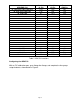
Figure 5. F/IC Aux Gauge Setup Connect the WHITE Analog Output + wire to the Aux Gauge input and the BROWN Analog Output – wire to the sensor ground. Table 4 below lists the Lambda and Sensor ground pin locations for the different FIC part numbers. AEM F/IC P/N 30-1910(X) 30-1930(X) Lambda Pin Pin 18 of 22-pin connector Pin 18 of 22-pin connector Pin 20 of 20-pin connector Sensor GND Pin Pin 5 of 22-pin connector Pin 5 of 22-pin connector Table 4.
Specifications UEGO Controller Supply Current (nominal, peak) 1.3A, 2.7A peak Differential Analog Outputs 1 Measuring Range 5.6 AFR E85 to 11.9 AFR E85 Sensor Accuracy 0.1 AFR Operating Voltage (nominal) 8.5-15 volts dc Harness & Connector Temp Limit: 105C Notes The sensor contains a ceramic module and should not be subject to mechanical or thermal shock or it may be damaged. The sensor is not designed for operation on leaded fuels, doing so will dramatically shorten sensor life.