
Manual


AEM Infinity Harness Manuals19
© 2014 AEM Performance Electronics
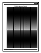
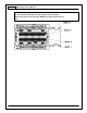
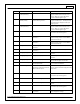
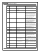
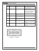
Infinity Pin
Hardware Ref.
Hardware Specification
Notes
See the 1D lookup table 'ShiftSwitch' for
setup. Also assignable to multiple functions.
See Setup Wizard for details.
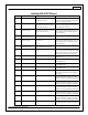
C1-75
Analog_In_10
12 bit A/D, 100K pullup to 5V
0-5V analog signal. Use +5V Out pins as power
supply and Sensor Ground pins as the low
reference. Do not connect signals referenced
to +12V as this can permanently damage the
ECU. See the Setup Wizard Barometric
Pressure page for setup and calibration.
Monitor the BaroPress [kPa] channel.
C1-76
Injector 3
Saturated (P/N 30-7108) or peak and
hold, 3A max continuous (P/N 30-
7106)
Injector 3
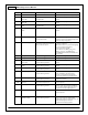
C1-77
Injector 2
Saturated (P/N 30-7108) or peak and
hold, 3A max continuous (P/N 30-
7106)
Injector 2
C1-78
Injector 1
Saturated (P/N 30-7108) or peak and
hold, 3A max continuous (P/N 30-
7106)
Injector 1
C1-79
Stepper_2A
Automotive, Programmable Stepper
Driver, up to 28V and ±1.4A
Be sure that each internal coil of the stepper
motor are properly paired with the 1A/1B and
2A/2B ECU outputs. Supports Bi-Polar stepper
motors only.
C1-80
Stepper_1A
Automotive, Programmable Stepper
Driver, up to 28V and ±1.4A
Be sure that each internal coil of the stepper
motor are properly paired with the 1A/1B and
2A/2B ECU outputs. Supports Bi-Polar stepper
motors only.