
Manual

AEM Infinity Harness Manuals17
© 2014 AEM Performance Electronics
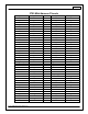
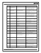
Infinity Pin
Hardware Ref.
Hardware Specification
Notes
C1-48
+12V_SW
10K pulldown
Full time battery power must be available at
C1-10 before this input is triggered.
C1-49
+5V_Out_1
Regulated, fused +5V supply for
sensor power
Analog sensor power
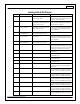
C1-50
+5V_Out_1
Regulated, fused +5V supply for
sensor power
Analog sensor power
C1-51
Analog_In_7
12 bit A/D, 100K pullup to 5V
0-5V analog signal. Use +5V Out pins as power
supply and Sensor Ground pins as the low
reference. Do not connect signals referenced
to +12V as this can permanently damage the
ECU. See the Setup Wizard Set Throttle Range
page for automatic min/max calibration.
Monitor the Throttle [%] channel. Also
DB1_TPSA [%] for DBW applications.
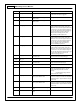
C1-52
Analog_In_8
12 bit A/D, 100K pullup to 5V
0-5V analog signal. Use +5V Out pins as power
supply and Sensor Ground pins as the low
reference. Do not connect signals referenced
to +12V as this can permanently damage the
ECU. See the Setup Wizard Set Manifold
Pressure page for setup and calibration.
Monitor the MAP [kPa] channel.
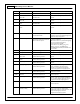
C1-53
Analog_In_9
12 bit A/D, 100K pullup to 5V
0-5V analog signal. Use +5V Out pins as power
supply and Sensor Ground pins as the low
reference. Do not connect signals referenced
to +12V as this can permanently damage the
ECU. See the Setup Wizard Fuel Pressure page
for setup and calibration. Monitor the
FuelPressure [psig] channel.
C1-54
VR+_In_2
Differential Variable Reluctance Zero
Cross Detection
See Non Driven Wheel Speed Calibration in
the Setup Wizard Vehicle Speed page.
C1-55
VR-_In_2
C1-56
VR-_In_3
Differential Variable Reluctance Zero
Cross Detection
See Driven Wheel Speed Calibration in the
Setup Wizard Vehicle Speed page.
C1-57
VR+_In_3
C1-58
HighsideSwitch_0
2.6A max, High Side Solid State Relay
See Setup Wizard page 'HighSide Assigment
Tables' for configuration options. See 2D
lookup table 'HS0_Table' for activation
settings.
See Setup Wizard page 'VTEC' for
default activation criteria.
C1-59
Stepper_1B
Automotive, Programmable Stepper
Driver, up to 28V and ±1.4A
Be sure that each internal coil of the stepper
motor are properly paired with the 1A/1B and
2A/2B ECU outputs. Supports Bi-Polar stepper
motors only.
C1-60
Stepper_2B
Automotive, Programmable Stepper
Driver, up to 28V and ±1.4A
Be sure that each internal coil of the stepper
motor are properly paired with the 1A/1B and
2A/2B ECU outputs. Supports Bi-Polar stepper
motors only.
C1-61
DBW1 Motor -
5.0A max Throttle Control Hbridge
Drive
+12V to close
C1-62
DBW1 Motor +
5.0A max Throttle Control Hbridge
Drive
+12V to open