Multi-Input Water/Methanol Injection Kit P/N 30-3350, 30-3351 ! WARNING: Improper installation and/or adjustment of this product can result in major engine/vehicle damage! Use of this injection system requires proper tuning! Use this system with EXTREME caution! If you are uncomfortable with anything about this, please refer the installation to an AEM trained tuning shop or call 800-423-0046 for technical assistance. You should also visit the AEM Performance Electronics Forum at http://www.aempower.
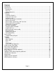
Contents Introduction ...................................................................................................................................3 Specifications ...............................................................................................................................3 Hardware Kit: ............................................................................................................................3 Parts List: .............................................................
Introduction Congratulations on your purchase of the AEM Water/Methanol Injection Kit. This document will help guide you through the setup and installation process. Please take the time to review its contents prior to installation. Pay especially close attention to any bolded text, as it indicates an important note, or step in the process. Before beginning installation of electronic components please disconnect the ground side of the battery. This is for your safety.
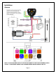
Installation Diagram NOTE: THIS KIT INCLUDES NEW STYLE INJECTOR NOZZLES THAT HAVE INTERNAL CHECK VALVES. AN EXTERNAL CHECK IS NO LONGER NEEDED OR INCLUDED IN THIS KIT.
Installation Checklist The following list of steps is an overview of the installation process. A complete and more detailed list of each step including optional peripherals is defined later in this document. □ Install Tank o Fasten with 4 of the 8 supplied #8 sheet metal screws along with the 4 large washers or the 5/16-18 bolts and Nylock nuts. □ Install Pump o Select suitable location for pump near and below the lowest fluid level of tank.
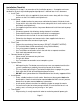
Pump and Tank Install Find a suitable location to mount the tank and pump. The tank should be mounted such that it is below the injection point. The tank and pump must be mounted in the same area. Pump may be mounted on exterior of vehicle but should be mounted away from wheel wells or other areas where it will come into direct contact with water or road debris. Pump failures that have clearly been caused by exposure to water/mud/debris will not be covered under warranty.
Take note of the direction of flow, indicated by the arrows on the pump body, when mounting the pump. Use four #8 sheet metal screws along with the 4 small washers or the #8-32 bolts and nylock nuts to mount the pump. The pump can be mounted in any position horizontally or vertically. Once the tank and pump are mounted, cut the appropriate length of tubing needed to connect the outlet fitting on the tank to the inlet fitting on the pump. Make sure there are no sharp bends in the tubing.
Progressive Controller Installation Pin # Description Wire** Color Connection 16 Orange Connect to ground (black) wire of pump. AWG 20 2 LED Gray Connect to ground (black) wire of external LED. AWG 20 3 LED + Violet Connect to positive (red) wire of external LED. AWG 20 1.5A Low Side output. Connect to optional flow control 4 Solenoid Brown/White AWG solenoid. Boost Safe LS 18 1.7A Low Side output. Grounded when error condition 5 Green Out AWG exists.
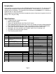
External MAP, Injector Duty, MAF overview The connection of the External MAP/MAF pin will depend on the desired mode of operation. Please follow the table in determining where to connect this wire. Mode of operation MAF / MAP (0V-5V) Dip Switch Settings ON – ON – ON Injector Duty (0%-100%) OFF – OFF – ON Frequency MAF (40Hz - 220Hz) Frequency MAF (400Hz – 2200Hz) Frequency MAF (2kHz – 14kHz) OFF – ON – OFF Pin Installation location *Connect to signal output from MAF/MAP where signal range is 0V-5V.
External MAP 0-5V Installation Operation: The 0 – 5 Volt external MAP mode is designed for vehicles running high boost, beyond that of the Internal and HD models, or for users who already have a sensor or output of their MAP with a range of 0 – 5 Volts. See Table 1 for compatible AEM MAP sensors. Dip Switch Settings: ON – ON – ON Setup, Connection: To setup your system for external MAP you must first find the correct source to connect to.
Injector Duty Installation Operation: The Injector Duty mode is designed for vehicles where water methanol injection rate is desired to be highly coupled to the injector duty, meaning the more fuel the more water methanol. This mode can be used when MAF is not available, or in NA vehicles. Injector duty is NOT intended to work with diesel or other multi-pulse injection systems.
0-5V MAF Installation Operation: The 0 – 5 Volt MAF mode is designed for vehicles where MAF is used and the output of their MAF sensor is 0-5V and not a frequency. Dip Switch Settings: Mode DIP Switches Common Applications 0 - 5 Volt ON – ON – ON VW/Audi 1.8T Subaru WRX/STi Nissan S13/S14/S15/300ZX Setup, Connection: To setup your system for MAF you must first find the correct source to connect too. In order to locate the correct signal the use of a voltmeter will be required.
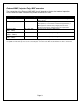
Frequency MAF Installation Operation: The Frequency MAF mode is designed for vehicles where MAF is used and the output of their MAF sensor is digital and a frequency. Dip Switch Settings: Mode Frequency MAF (40Hz - 220Hz) Frequency MAF (400Hz – 2200Hz) Frequency MAF (2kHz – 14kHz) DIP Switches Common Applications OFF – ON – OFF 1993 and older GM OFF – ON – ON ON – OFF – OFF 1990 – 1999 Mitsu 1G/2G DSM 1994+ GM VW 2.
Pump/Tank Flush After all wires are hooked up, add water to the tank and with the hose pointed into a container, press and hold the “TEST” push button on the controller module. The “TEST” button can be used to test the system. The pump speed will gradually increase from zero to full speed over 3 seconds, and then remain full for another 3 seconds before stopping. Repeat the “TEST” button procedure until you are sure the system is free of any debris that may have been in the lines or tank.
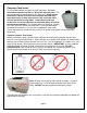
Nozzle Mounting Select the location where the nozzle will be installed. Nozzle should be mounted such that it is higher than the tank. Nozzle must be mounted before the throttle plate. Nozzle should also be mounted after the MAF sensor if present. Nozzle must also be mounted after any intercoolers. In most instances, mounting the nozzle 6-8” ahead of the throttle body provides an excellent combination of air charge cooling and combustion control.
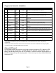
System Errors The controller will continuously check for errors; when an error is detected it will be reported to the user by a flashing sequence of the external LED, as well as a corresponding red flashing sequence of the status LED. Damage to vehicle or engine may occur if these faults are not resolved immediately. The water-injection system may not operate properly or at all while an error condition exists. Please refer to the table below for further information.
Troubleshooting Diagram Page 17
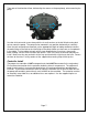
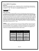
Controller Settings The AEM Water Methanol Injection Controller is a progressive type controller. This means that fluid will be injected in proportion to the amount of boost that is detected by the external MAP input. In other words, higher signal input equals more fluid. It is therefore imperative that the external signal connection be made properly and securely or vehicle/engine damage could occur.
Fuse The controller has an externally accessible fuse. The controller itself will turn on and function, but the pump will not run without the fuse. If the controller is reporting an open circuit it may be that the fuse has blown, and or is not installed correctly. Use a 15 amp fast blow fuse for replacement purposes. “Test” Button The Test button feature is available to test the systems functionality. This feature should be used ONLY with the nozzle disconnected from the engine.
Boost-Safe Output (optional) The progressive controller includes a Boost-Safe output (grounded when active) that activates whenever the system is armed and runs out of fluid or an error code is flashing. The green wire on the controller is the 1.7 amp switched ground. This wire can be hooked up to a solenoid that will vent waste gate pressure when activated. Apply 12v to the other side of the solenoid (AEM P/N 30-2400 or equivalent).
Important Safety Notice Regarding Methanol AEM strongly recommends that users never exceed a 50% methanol concentration when using any AEM Water Methanol system or component. All AEM water/methanol injection systems and components (pump, lines, fittings, filter, flow sensor, tank, and nozzles) are 100% chemically compatible with methanol. However, for safety reasons we strongly recommend that users never use more than a 50% methanol concentration in our systems.
Optional System Upgrades Water/Methanol Injection FAILSAFE Device AEM P/N 30-3020/30-3020M Actively monitors the entire flow curve independent of pressure, continuously collecting flow vs. injection rate data so that any deviation from your established flow curve will trigger an alarm output that can be used to reduce boost or timing, change maps, add fuel, trigger a two-step or perform practically any action you choose to save your engine.
AEM Electronics warranty Advanced Engine Management Inc. warrants to the consumer that all AEM High Performance products will be free from defects in material and workmanship for a period of twelve (12) months from date of the original purchase. Products that fail within this 12-month warranty period will be repaired or replaced at AEM’s option, when determined by AEM that the product failed due to defects in material or workmanship. This warranty is limited to the repair or replacement of the AEM part.