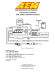
Part Number 30-2320 AEM X-WIFI UEGO/EGT Module Figure 1. Wiring Schematic AEM X-WIFI Parts 1 x 30-2320 X-WIFI Module 1 x 30-2001 UEGO Sensor 1 x 35-8535 Install Kit (UEGO Bung and 6 Butt Connectors) 1 x 10-2320 Installation Instructions 1 x 35-3416 8-Pin Power Harness 1 x 35-3400 6-Pin UEGO Sensor Harness 1 x 35-3009 USB Cable 4 x Zip Tie AEM Performance Electronics 2205 126th Street Unit A, Hawthorne, CA. 90250 Phone: (310) 484-2322 Fax: (310) 484-0152 http://www.aemelectronics.
INSTALLATION 1. Disconnect the negative battery cable. 2. Find a suitable, in cab, mounting location and secure the X-WIFI module using the supplied zip ties. Note: The X-WIFI is not weatherproof and should not be mounted in the engine bay or exposed to outside elements 3. Plug the 8-pin power harness into the mating connector on the right side of the XWIFI and connect the wires as shown in Figure 1. 4. Mount the UEGO sensor as shown in figure 3. 5.
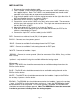
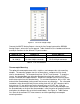
Displaying Data with WIFI Enabled Electronic Devices Real time AFR and EGT data from the X-WIFI can be viewed on WIFI enabled electronic devices using a standard web browser. Locate the network “AEM X-WIFI” and connect. Type the address 192.168.3.88 in the address bar of the browser and open the web page. A screen showing the AFR and EGT values will appear as shown below in Figure 2. If a UEGO sensor error is detected, the AFR value will display “Err” followed by a number.
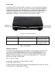
Status Lights The AEM X-WIFI has two status lights, see Figure 4. The warm up status light on the left flashes during sensor warm up. Once the sensor reaches operating temperature, usually within 30 seconds, the light will remain on. During sensor warm up, AFR readings may not be accurate. The UEGO error status light on the right will flash if a sensor error is detected. The status light will flash on and off a number of times, followed by a short pause. The error codes are listed below in Table 1.
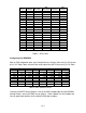
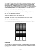
VOLTS 0.50 0.71 0.92 1.13 1.34 1.55 1.76 1.97 2.18 2.39 2.61 2.82 3.03 3.11 3.24 3.45 3.66 3.87 4.08 4.29 4.50 LAMBDA 0.58 0.61 0.65 0.68 0.71 0.75 0.78 0.82 0.85 0.88 0.92 0.95 0.99 1.00 1.02 1.05 1.09 1.12 1.16 1.19 1.22 AFR GAS 8.5 9.0 9.5 10.0 10.5 11.0 11.5 12.0 12.5 13.0 13.5 14.0 14.5 14.7 15.0 15.5 16.0 16.5 17.0 17.5 18.0 AFR METHANOL 3.7 3.9 4.1 4.4 4.6 4.8 5.0 5.2 5.4 5.7 5.9 6.1 6.3 6.4 6.5 6.7 7.0 7.2 7.4 7.6 7.8 AFR E85 5.6 5.9 6.3 6.6 6.9 7.3 7.6 7.9 8.2 8.6 8.9 9.2 9.6 9.7 9.9 10.2 10.
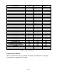
AEM EMS P/N 30-1000/1001/1002/1040/1042 30-1010/1012/1050/1052 30-1020/1060 30-1030/1031/1070 30-1080 30-1081 30-1100/1101 30-1110 30-1120/1121/1130 30-1220 30-1300 30-1310/1311/1312/1313 30-1320 30-1400 30-1401 30-1510 30-1600/1601/1602/1603 30-1610/1611/1612 30-1620/1621/1622/1623 30-1710 30-1720 30-1800 30-1810 30-1820/1821 30-6100/30-6101 30-6010/6012/6050/6052 30-6000/6001/6002/6040/6042 30-6060 30-6310/30-6311/30-6313 30-6320 Lambda #1 Pin D14 C16 D7 C13 C16 C16 B47 1C B6 30 4 76 71 29 44 C2-31 19 46
Figure 5. F/IC Aux Gauge Setup Connect the WHITE Analog Output + wire to the Aux Gauge input and the BROWN Analog Output – wire to the sensor ground. Table 4 below lists the Lambda and Sensor ground pin locations for the different FIC part numbers. AEM F/IC P/N 30-1910(X) 30-1930(X) Lambda Pin Pin 18 of 22-pin connector Pin 18 of 22-pin connector Pin 20 of 20-pin connector Sensor GND Pin Pin 5 of 22-pin connector Pin 5 of 22-pin connector Table 4.
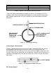
EGT Measurement Individual Cylinder EGT Turbine Inlet Temperature Cylinder Bank EGT Mounting Location 1-2 inches from exhaust port 2-3 inches from turbine inlet Header collector Table 5. Common Thermocouple Mounting Locations When using both thermocouples for comparison (bank 1 EGT and bank 2 EGT for example), make sure to mount both thermocouples in a similar fashion (distance from port, tip depth, tube diameter, etc) so the readings are not influenced by installation differences.
The analog EGT outputs from the AEM X-WIFI are linear dc voltage signals that vary from 0.5 Vdc at 0 Degrees Fahrenheit (-18 Degrees Celsius) to 4.5Vdc at 1800 Degrees Fahrenheit (982 Degrees Celsius) over the operating range of the X-WIFI. The signals are used for sending information to a data logger or an engine management system like the AEM EMS or F/IC. The transfer functions for the analog outputs are listed below in Degrees Fahrenheit and Degrees Celsius.
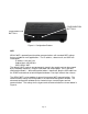
CONFIGURATION BUTTON 2 CONFIGURATION BUTTON 1 Figure 8. Configuration Buttons WIFI AEM X-WIFI is preconfigured for adhoc communications with standard WIFI settings that are suitable for most applications. The IP address, subnet mask, and SSID are listed below: IP address: 192.168.3.88 Subnet Mask: 255.255.0.0 SSID: AEM X-WIFI The default X-WIFI settings are permanently stored in the module and can be restored by the following sequence. Plug the USB cable into the pc/laptop.
FIGURE 9. HYPER TERMINAL SETTINGS To view the advanced configuration screen, open the hyper terminal communication, but do not connect. Plug the USB cable into the pc/laptop. Press and hold configuration button 1. With configuration button 1 depressed, plug the USB cable into the X-WIFI and continue to hold configuration button 1 for two seconds, then release. Click the connect button on the hyper terminal communication. The advanced configuration screen will appear as shown below in Figure 10. FIGURE 10.
Displaying Data with a PC/Laptop Real time AFR and EGT data can also be viewed via a pc/laptop with USB connection. See figure 11. Download the data viewer program and instructions from the AEM Performance Electronics forum at www.aemelectronics.com. Portable Power ConnectionFigure 11. PC Data Viewer The AEM X-WIFI has an on-board barrel connector that can be used to power the module using a 5 amp 12Vdc power supply when a hard wired power connection is not desired. The power supply must have a 2.
Figure 13. Harness Pinouts Specifications X-WIFI Supply Current (nominal, peak) Differential Analog Outputs Measuring Range: UEGO UEGO Sensor Accuracy Measuring Range: EGT 1.5A, 3A peak 3 8.5:1 to 18:1 AFR Gasoline, 0.58-1.22 Lambda 0.1 AFR 0 – 1800 Degrees Fahrenheit, -18-982 Degrees Celsius EGT Sensor Accuracy 0.75% FS Operating Voltage (nominal) 8.
12 MONTH LIMITED WARRANTY Advanced Engine Management Inc. warrants to the consumer that all AEM High Performance products will be free from defects in material and workmanship for a period of twelve (12) months from date of the original purchase. Products that fail within this 12month warranty period will be repaired or replaced at AEM’s option, when determined by AEM that the product failed due to defects in material or workmanship. This warranty is limited to the repair or replacement of the AEM part.