Installation Instructions for 30-1930 Fuel Ignition Controller (F/IC) ! WARNING: This installation is not for the electrically or mechanically challenged! Use the F/IC with EXTREME caution! If you are uncomfortable with anything about this, please refer the installation to an AEM trained tuning shop or call 800-423-0046 for technical assistance. You should also visit the AEM Performance Electronics Forum at http://www.aempower.
Thank you for purchasing the AEM F/IC. Inside the box you will find the F/IC module, a universal wiring harness, a software CD, and other components needed to install the F/IC and adjust the FIC via a laptop or PC. See Figure 1. For more information on select vehicles, please visit the FIC section of the AEM Electronics Forum. The forum can be accessed from the AEM homepage (www.aempower.com), by clicking on the link titled “Forums”.
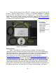
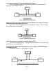
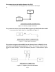
WIRE CONNECTIONS TO FIC TO FIC TO ENGINE TO ECU TO ENGINE TO ECU CUT WIRE INTERCEPT TAP Figure 2. Wire Connections Does your vehicle have a Mag/VR or Hall style Crank Sensor? Magnetic(Mag) or Variable Reluctance(VR) style sensors typically have two wires. Hall style sensors typically have three wires. Vehicles have either a Mag/VR or a Hall style Crank Sensor, not both. If your vehicle has a Mag/VR sensor, the two Hall sensor wires can be eliminated.
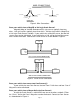
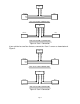
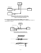
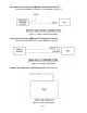
FIC CAM1 HALO + CAM1 HALI + SENSOR ECU SIGNAL VREF GND HALL STYLE CAM 1 CONNECTION FIC CAM1 MAGO + CAM1 MAGO - CAM1 MAGI - CAM1 MAGI + SENSOR ECU + - MAG STYLE CAM 1 CONNECTION Figure 4. Cam 1 Connection If your vehicle has two Cam Sensors, connect the “Cam 2” sensor as shown below in Figure 5. FIC CAM2 HALO + CAM2 HALI + SENSOR ECU SIGNAL VREF GND HALL STYLE CAM 2 CONNECTION FIC CAM2 MAGO + CAM2 MAGO - CAM2 MAGI - CAM2 MAGI + SENSOR + - MAG STYLE CAM 2 CONNECTION Figure 5.
Do you want to modify or clamp the MAF Sensor voltage? If not, the two MAF Sensor wires can be eliminated. If so, connect the MAF Sensor as shown below in Figure 6. FIC MAF OUT + MAF IN + SENSOR ECU SIGNAL (+) VREF GND MAF CONNECTION Figure 6. MAF Sensor Connection Does your vehicle have both a MAP Sensor and a MAF Sensor? or Do you want to remap another analog signal on your car? If so, connect the “Analog A/B” wires as shown below in Figure 7. If not, remove the unused wires for “Analog A/B”.
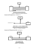
FIC INJ 1 OUT INJ 1 IN PRIMARY FUEL INJECTOR 1 ECU FUEL INJ 1 TO +12V SECONDARY FUEL INJECTOR 1 TO +12V SECONDARY FUEL INJECTOR CONNECTION Figure 8. Fuel Injector Connection Do you want to modify the Oxygen(O2)/UEGO sensor signals? If not, the “O2” sensor wires can be eliminated. If so, connect the sensors as shown below in Figure 9. .
FIC O21 + SENSOR ECU NERNST CELL POWER TO FACTORY HARNESS WIDE BAND O2 SENSOR CONNECTION Figure 9. Oxygen/UEGO Sensor Connection Connect the F/IC power wire. See Figure 10. FIC IGN PWR TO SWITCHED +12V ECU SW +12V SWITCHED +12 VDC CONNECTION Figure 10. F/IC Power Connection Connect the TPS signal to the F/IC. See Figure 11. FIC TPS + ECU SENSOR SIGNAL VREF GND TPS CONNECTION Figure 11.
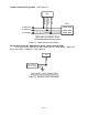
Connect all three F/IC grounds. See Figure 12. FIC SIG GND PWR GND PWR GND ECU TO GROUND POWER GND TO GROUND POWER GND TO SIG GND SIGNAL GND GROUND CONNECTION Figure 12. Power Ground Connections Do you want to use the Switched 12 volt dc source from the F/IC? If so, connect the “Switched 12 Volt” source wire as shown below. (Note: The driver can handle 1 amp Max.) See Figure 13. FIC SW12 LOW CURRENT RELAY/SOLENOID SWITCHED 12 VDC CONNECTION Figure 13.
Do you want to use the Auxiliary Gauge in the F/IC? If so, connect the “Auxiliary Input” as shown below. See Figure 4. FIC AUX IN UEGO 0-5V OUT AUXILIARY GAUGE CONNECTION Figure 14. Auxiliary Gauge Connection Do you want to use the F/IC’s Internal Data Logger or the Dual Calibration mode? If so, connect the “Switch Input” as shown below in Figure 15. Figure 15.
Do you want to control the AEM boost solenoid with the FIC? If so, connect the boost solenoid as shown below in Figure 17. Figure 17. Boost Solenoid Connection Do you want to use the AEM Inlet Air Temperature sensor? If so, connect the AEM IAT as shown below in Figure 18. Figure 18. Analog C connection Connect the boost line to manifold pressure. See Figure 19. Figure 19.
Connect the F/IC to the PC using the supplied USB cable. See Figure 20. Figure 20. USB Com Cable Connection Using the F/IC The F/IC is a very unique product, capable of precise Fuel and Ignition Control. However, the F/IC, by design, is a “piggyback” engine controller, not a stand-alone ECU. Because it is a piggyback controller, the F/IC relies heavily on the factory ECU.
When talking pressure, there are two common ways pressure is represented, Gauge, and Absolute, Gauge being by far the more common way. Take a tire for example, if the measuring gauge says 50 psi, we say the tire has 50 psi of air in it. However, that is not 100% correct. The tire actually has air at 50 psi above atmospheric pressure, which is known as psi gauge (psig). The total pressure, or absolute pressure (psia) is actually 50 psi on the gauge plus the atmospheric pressure.
Figure 21. Open File Saving a Calibration under a different name With a Calibration open, go to File>Save-As. Select a file name and location to save the file in the “Save As” pop-up window. See Figure 22. Figure 22. File Save As Editing a Calibration The FIC has 8 user configurable maps. Each map is 21X17 and has user configurable Load and RPM Breakpoints. The map cells have a white background, while the Load and RPM Breakpoints have a gray background. See Figure 23.
Figure 23. Map Cells and Breakpoints To edit Breakpoints, double click on a breakpoint. The background for the breakpoints will change from gray to white, signifying that the breakpoints can now be edited. See Figure 24. Figure 24. Editing Breakpoints To change the value of a Breakpoint, select the breakpoint and type in the new value. Breakpoints can be selected using the arrow keys or the mouse. To linearly interpolate between breakpoints, highlight the desired breakpoints by using the left mouse button.
· · · · · · · · CTRL-M = Show MAF map screen CTRL-O = Show O2 map screen CTRL-S = Show Setup screen CTRL-U = Value-up CTRL-V = Paste from clip board CTRL-X = Show value-change pop-up menu CTRL-Y = Redo CTRL-Z = Undo Fuel Map, MAP Load (See Figure 25.) The MAP based “Fuel Map” uses the onboard map sensor for its load input. Fuel can be added or removed from the engine based on engine speed and manifold pressure.
Ignition map (See Figure 26.) The “Ignition Map” is used to Retard Ignition Timing. The load input for the “Ignition Map” is based on either MAP, MAF, or TPS. Timing will be removed from the engine based on the selected load input and engine speed. Since timing can only be removed(retard) from the engine, the “Ignition Map”only accepts negative numbers. For example, a value of –4 will retard the timing 4 degrees. The load input for the “Ignition Map”is selected from the “Setup” window.
“Percent” mode - The F/IC will measure the input voltage on the Analog A(B) input wire and modify the output voltage by the value in the Analog A(B) map. For an input voltage of 1 volt, a cell value of 6, the output voltage will be 1.06 volts. “Voltage” mode - The F/IC will output the voltage value that is in the “MAF Map”. For example, the F/IC will output 2.5 volts for a value of 2.5 in the Analog A(B) map.
Bank Lo of 1, a period of 200 ms, and a cell value of 50, the F/IC will output 2 volts for 50 ms, 1 volt for 150ms, 2 volts for 50 ms, etc. “Percent” mode - The F/IC will measure the O2 voltage, then modify it by the percentage value in the “O2 Map”. For a measured value of 1 volt, a period of 200ms, and a cell value of 20, the F/IC will measure 1 volt for 5ms, then output 1.2 volts for 195ms, then measure again for 5ms, etc.
Figure 29. AFR to Voltage Table. Frequency Map (See Figure 30.) The Frequency Map is used to output a frequency signal from the FIC to the factory ECU. The frequency functionality is intended for vehicles with frequency based MAF sensors, such as Karman Vortex or GM Delphi. Using the Frequency Map, the FIC can mimic, alter, or clamp the input frequency signal.
Figure 30. Frequency Map Boost Map (See Figure 31) The FIC8 has a pulse width modulated output that will drive the AEM boost solenoid (P/N 30-2400) at varying duty cycles based on the Boost Map. The values entered into the Boost Map are duty cycle values between 0 and 100%. The Boost Map load input can be based on TPS, Analog C, or RPM. When RPM is selected, the Boost Map has no load input. For a cell value of 30, the FIC outputs a signal at 30% duty cycle.
Figure 31. Boost Map Using Passwords The FIC has user selectable password capabilities. To add a password to a non password file, click File>Change Cal-File PIN and follow the on-screen instructions. When prompted, enter the new PIN. PIN’s are case sensitive. When opening an existing file with a PIN, the software will prompt the user to enter the PIN before fully opening the file. An error window will appear if an incorrect PIN is entered.
Configuring the FIC With the FIC software open, select Setup>System. See Figure 32. Figure 32. F/IC Setup Window Com Port: Displays the com port to which the F/IC is connected. This value will automatically be entered once the F/IC is connected to the computer. Load Display Units: The on board map sensor reads load in absolute pressure. The load can be displayed in PSI absolute or KPA absolute. User Switch Input Function: Select the functionality for the User Switch Input Function.
MAF: Select the load input and operating mode for the MAF map. Set the maximum voltage clamp (max output voltage) for the MAF map. Analog A(B): Select the load input and operating mode for the Analog A(B) map. Analog C: Set the “Units name” for the Analog C input. Turn the 2.2Kohm pull-up resistor on and off. Open the Analog C voltage table O2: Select the load input and operating mode for the O2 map. Set the period for the fixed and percentage modes. Set the high and low voltages for bank 1 and bank 2.
Connecting to the FIC: (Note: when connecting to the FIC for the first time, the found new hardware window will appear. The USB drivers will load automatically.) Connect the FIC to the PC using the supplied USB cable. With a calibration already open, click on the connect button to connect to the F/IC. See Figure 33. Figure 33.
Uploading a Cal File: This function is used to upload a calibration only. To upload a cal file to the FIC, click on file and select “Upload Cal Only”. Select the file to upload and click open. Note: When using the “Upload Cal Only” function, the software will overwrite the calibration in the FIC with the selected calibration. Calibrating the FIC: When an FIC is installed on a vehicle, it is necessary to calibrate the FIC before any tuning is performed.
Gauges Window: To aid in tuning, the FIC software has a Gauges window that gives real-time reference to the engine’s operating conditions. See Figure 35. Figure 35. F/IC Gauges Window The Gauges window contains a user configurable Tachometer, Pressure(Load) gauge, and an Auxiliary gauge (UEGO in Fig. 32), along with real-time displays of TPS, MAF volts, O2 volts, Switched 12Vdc status, Battery volts, Fuel Trim, Analog A, Analog B, and Ignition trim.
Figure 36. Auxiliary Gauge Setup The Auxiliary gauge uses a 10 position calibration. Enter the input voltage value into the “Volts In” column. Enter the value to be displayed for each input voltage in the corresponding row of the “Meter Value” column. The appearance of the gauge is configured by parameters on the left side of the “Aux gauge setup” window. The Face Name is displayed in bold letters just above the center of the gauge. The units are displayed in smaller letters below the center of the gauge.
Figure 37. Analog C Voltage Table Date Logging: There are two types of logging available with the FIC, Internal and PC logging. In both modes of logging, the parameters that appear in the “Gauges” window are logged. Internal Logging: The FIC contains an onboard 2 MB logger. The sampling rate and trip conditions for the onboard logger are set in the “FIC Logger” section of the “Setup” window. The sampling rate can be set from 10mS to 1275mS. Sampling every 10mS will give four minutes of data.
PC Logging: The FIC software allows you to log data to your PC while connected to the FIC. The sampling rate and file size are determined by the available memory and processor speed of the PC. To start PC logging, go to Logger>PC Logger Start. To stop PC logging go to Logger> PC Logger Stop, give the file a name and save it. Logged files are saved as delimited text files. Dual Calibration: The FIC has a “Dual Calibration” mode, which allows the user to switch between two maps with the flip of a switch.
Appendix Oxygen Sensor theory. Wide-band: A wide-band sensor works by servo operation between a measuring cell (Nernst cell) and an oxygen pumping cell. These two cells are contained in the O2 sensor where the exhaust gas is sampled by a chamber connecting the two cells. The controller in the car will change the current applied to the pump cell in an attempt to keep the Nernst cell voltage at a predetermined level.
Pin 1 2 3 4 5 6 7 8 9 10 11 12 13 14 15 16 17 18 19 20 21 22 Name Fuel injector 1 input Hall style sensor Cam 2 output Hall style sensor Cam 1 output Power GND Signal GND TPS input Hall style sensor Crank input Mag style Crank sensor negative input Mag style sensor Cam 2 positive output Mag style sensor Crank negative output Mag style sensor Cam 1 negative output Fuel injector 2 input User Switch Input Hall style Crank sensor output Power GND Ignition power Analog B out Aux Input Mag style crank sensor pos
Pin 1 2 3 4 5 6 7 8 9 10 11 12 13 14 15 16 17 18 19 20 21 22 23 24 Name Bank 2 oxygen sensor modifier Analog B in Analog A out Hall style Cam 2 sensor input Mag style Cam 2 sensor positive input Analog A in Mag Style Cam 2 sensor negative input Hall style Cam 1 sensor input Mag style Cam 1 sensor positive input Mag style Cam 1 sensor negative input Fuel injector 5 input Fuel injector 3 input Banks 1 oxygen sensor modifier MAF signal input MAF signal output Switched 12Vdc output Fuel injector 6 output Fuel
Pin 1 2 3 4 5 6 7 8 9 10 11 12 13 14 15 16 17 18 19 20 Name Fuel injector 7 signal in Fuel injector 8 signal in Fuel injector 7 signal out Fuel injector 8 signal out Cam3 signal in +, MAG Cam3 signal in -, MAG Cam3 signal in +, HALL Cam4 signal in +, MAG Cam4 signal in -, MAG Cam4 signal in +, HALL Cam3 signal out -, MAG Cam3 signal out +, MAG Cam3 signal out +, HALL Cam4 signal out -, MAG Cam4 signal out +, MAG Cam4 signal out +, HALL Boost solenoid driver Frequency output Frequency input Aux analog-C Wi
AEM Electronics warranty Advanced Engine Management Inc. warrants to the consumer that all AEM High Performance products will be free from defects in material and workmanship for a period of twelve (12) months from date of the original purchase. Products that fail within this 12-month warranty period will be repaired or replaced at AEM’s option, when determined by AEM that the product failed due to defects in material or workmanship. This warranty is limited to the repair or replacement of the AEM part.