
Owner's manual

Page 28
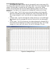
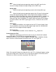
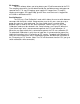
Figure 42: Auxiliary gauge setup
The Auxiliary gauge uses a 10 position calibration. Enter the input voltage value into the
“Volts In” column. Enter the value to be displayed for each input voltage in the
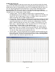
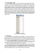
corresponding row of the “Meter Value” column. The appearance of the gauge is
configured by parameters on the left side of the “Aux gauge setup” window. The Face
Name is displayed in bold letters just above the center of the gauge. The units are
displayed in smaller letters below the center of the gauge. “Digit_DP” sets the number of
decimal places displayed by the large bold numbers at the bottom of the gauge.
“Scale_DP” sets the number of decimal places displayed by the tick mark values on the
gauge face. “Scale max” and “Scale min” set the display range of the gauge. “Scale
major ticks” and “Scale minor ticks” set the number of major and minor tick marks
displayed on the gauge. “Yellow start” and “Red start” set the starting value for the
yellow and red regions of the gauge. “Alarm” sets the value at which the gauge needle
starts flashing.
Data Logging:
There are two types of logging available with the F/IC, Internal and PC logging.
In both modes of logging, the parameters that appear in the “Gauges” window are
logged.
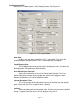
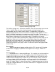
Internal Logging:
The F/IC contains an onboard 64KB logger. The sampling rate and trip conditions
for the onboard logger are set in the “FIC Logger” section of the “Setup” window. The
sampling rate can be set from 10mS to 1275mS. Sampling every 10mS will give 10.23
seconds of data. Sampling every 1275mS will give 21.73 minutes of data. In order to
start internal logging, all the trip conditions must be met and the “User Switch Input”
must be grounded. (Note: When using the “User Switch Input” in the “Dual Calibration”
mode, the” Logger Trigger” is always on by default.) To download data from the Internal
logger, go to Logger>Download FIC and save the file to the PC. Logged files are saved
as delimited text files.