
Owner's manual

Page 21
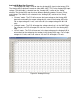
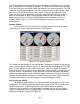
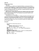
Analog A(B) Map (See Figure 34)
The Analog A(B) map is used to alter the Analog A(B) signal to the factory ECU.
The Analog A(B) map load is based on either MAP, MAF, TPS, or the Analog A(B) input
voltage. The load input is selected from the “Analog A(B)” section of the “Setup”
window. The Analog A(B) map has three different operating modes, Percent, Offset,
and Voltage. The mode is also selected in the “Analog A(B)” section of the “Setup”
window.
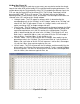
“Percent” mode - The F/IC will measure the input voltage on the Analog A(B)
input wire and modify the output voltage by the value in the Analog A(B) map.
For an input voltage of 1 volt, a cell value of 6, the output voltage will be 1.06
volts.
“Voltage” mode - The F/IC will output the voltage value that is in the “MAF Map”.
For example, the F/IC will output 2.5 volts for a value of 2.5 in the Analog A(B)
map.
“Offset” mode - The F/IC will measure in the input voltage on the Analog A(B) in
wire and offset the voltage by the number in the Analog A(B) map. For an input
voltage of 1.5 volts and a cell value of .25, the F/IC will output 1.75 volts.
Figure 34: Analog A/B map