Installation Instructions for 30-1910 Fuel Ignition Controller (F/IC6) Rev August, 2013 ! WARNING: This installation is not for the electrically or mechanically challenged! Use the F/IC with EXTREME caution! If you are uncomfortable with anything about this, please refer the installation to an AEM trained tuning shop or call 800-423-0046 for technical assistance. You should also visit the AEM Performance Electronics F/IC Forum at http://forum.aempower.com/forum/index.php?board=89.
Thank you for purchasing the AEM F/IC6. Inside the box you will find the F/IC module, a universal wiring harness, and other components required to install the F/IC and adjust the F/IC via a laptop or PC. See Figure 1. Please note that all hyperlinks in the PDF version of this instruction manual are accessible by clicking on them. For more information on select vehicles, please visit the F/IC section of the AEM Electronics Forum here: http://forum.aempower.com/forum/index.php?board=89.0.
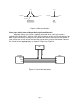
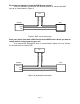
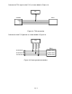
TO FIC TO ENGINE TO FIC TO ECU TO ENGINE TO ECU CUT WIRE INTERCEPT TAP Figure 2: Wire connections Does your vehicle have a Mag or Hall style Crank Sensor? Magnetic (Mag) style sensors typically have two wires. Hall style sensors typically have three wires. Vehicles have either a Mag or a Hall style Crank Sensor, not both. If your vehicle has a Mag sensor, the two Hall sensor wires can be eliminated. If your vehicle has a Hall sensor the four Mag sensor wires may be eliminated.
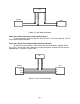
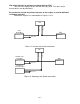
FIC CRK MAGO + CRK MAGI - CRK MAGI + SENSOR ECU + - Figure 4: Crank Mag connection Does your vehicle have one or two Cam Sensor(s)? If your vehicle has one Cam Sensor, the two “Cam 2” Hall wires and four “Cam 2” Mag wires may be eliminated. Does your vehicle have a Mag or Hall style Cam Sensor? As with the Crank Sensor, a vehicle will have one or the other, not both. Either the “Cam 1” Hall or the Cam 1 Mag wires can be eliminated. Connect the Cam Sensor appropriately as shown in Figure 5 or 6.
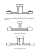
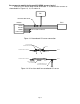
FIC CAM1 MAGO + CAM1 MAGI - CAM1 MAGI + SENSOR ECU + - Figure 6: Cam 1 Mag connection If your vehicle has two Cam Sensors, connect the “Cam 2” sensor as shown below in Figure 7 or 8.
Do you want to modify or clamp the MAF Sensor voltage? If not, the two MAF Sensor wires can be eliminated. If so, connect the MAF Sensor as shown below in Figure 9. FIC MAF OUT + MAF IN + SENSOR ECU SIGNAL (+) VREF GND Figure 9: MAF sensor connection Does your vehicle have both a MAP Sensor and a MAF Sensor? Or do you want to remap another analog signal on your car? If so, connect the “Analog A/B” wires as shown below in Figure 10. If not, remove the unused wires for “Analog A/B”.
How many injectors do you want to control with the F/IC? The F/IC has 6 Injector drivers with two wires per driver. The wires for the unused drivers can be eliminated. Do you want to control the primary injectors on the engine, or control additional secondary injectors? Connect the injectors as shown below in Figure 11 or 12.
Do you want to modify the Oxygen(O2)/UEGO sensor signals? If not, the “O2” sensor wires can be eliminated. If so, connect the sensors as shown below in Figures 13, 14, 15 and/or 16.
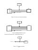
FIC O21 + SENSOR ECU SIGNAL + SIGNAL HEATER POWER TO FACTORY HARNESS Figure 15: Current sync O2 sensor connection FIC O21 + SENSOR ECU NERNST CELL POWER TO FACTORY HARNESS Figure 16: Wideband UEGO O2 sensor Connect the F/IC power wire as shown below in Figure 17.
Connect the TPS signal to the F/IC as shown below in Figure 18. FIC TPS + ECU SENSOR SIGNAL VREF GND Figure 18: TPS connection Connect all three F/IC grounds as shown below in Figure 19.
Do you want to use the Switched 12 volt DC source from the F/IC? If so, connect the “Switched 12 Volt” source wire as shown below. (Note: The driver can handle 1 amp max.) See Figure 20. FIC SW12 LOW CURRENT RELAY/SOLENOID Figure 20: Switched 12VDC connection Do you want to use the Auxiliary Gauge in the F/IC? If so, connect analog UEGO AEM no. 30-5130 as shown below. See Figure 21.
Or connect the “Auxiliary Input” as shown below. See Figure 23. FIC AUX IN UEGO 0-5V OUT Figure 23: Auxiliary gauge connection Do you want to use the F/IC’s Internal Data Logger or the Dual Calibration mode? If so, connect the “Switch Input” as shown below in Figure 24. FIC SW IN Figure 24: Switch input connection Connect the “Boost Line” to manifold pressure (After Throttle Body) as shown below in Figure 25.
Connect the F/IC to the PC using the supplied USB cable. See Figure 26.
Using the F/IC The F/IC is a very unique product, capable of precise Fuel and Ignition Control. However, the F/IC, by design, is a “piggyback” engine controller, not a stand-alone ECU. Because it is a piggyback controller, the F/IC relies heavily on the factory ECU. As factory ECU’s get more and more complex, it is more difficult to sustain improved engine performance without the factory ECU “detuning” the engine. Thus, the key to using the F/IC is to make it work in harmony with the factory ECU.
Now that you’re starting to grasp absolute pressure, you might wonder why the F/IC reads absolute pressure. Well, absolute pressure is the only accurate, repeatable way to measure manifold pressure. Measuring only “Boost” pressure does not account for changes in atmospheric pressure. Changes in atmospheric pressure will cause changes in manifold pressure. For example, let’s consider a boost gauge at high elevation, where atmospheric pressure is 12.7 psia.
Saving a Calibration under a different name With a Calibration open, go to File>Save As. Select a file name and location to save the file in the “Save As” pop-up window. See Figure 28. Figure 28: File Save As Editing a Calibration The F/IC has 6 user configurable maps. Each map is 21X17 and has user configurable Load and RPM Breakpoints. The map cells have a white background, while the Load and RPM Breakpoints have a gray background. See Figure 29.
To edit Breakpoints, double click on a breakpoint. The background for the breakpoints will change from gray to white, signifying that the breakpoints can now be edited. See Figure 30. Figure 30: Editing breakpoints To change the value of a breakpoint, select the breakpoint and type in the new value. Breakpoints can be selected using the arrow keys or the mouse. To linearly interpolate between breakpoints, highlight the desired breakpoints by using the left mouse button.
Fuel Map, MAP Load (See Figure 31) The MAP based “Fuel Map” uses the onboard map sensor for its load input. Fuel can be added or removed from the engine based on engine speed and manifold pressure. With a value of 12% in any of the cells, the F/IC will hold the injector open for 12% longer than the factory fuel pulse. With a value of -18% in any of the cells, the F/IC will hold the injector open for 18% less time than the factory fuel pulse.
Ignition map (See Figure 32) The “Ignition Map” is used to Retard Ignition Timing. The load input for the “Ignition Map” is based on MAP, MAF, or TPS. Timing will be removed from the engine based on the selected load input and engine speed. Since timing can only be removed (retarded) from the engine, the “Ignition Map” only accepts negative numbers. For example, a value of –4 will retard the timing 4°. The load input for the “Ignition Map” is selected from the “Setup” window.
MAF Map (See Figure 33) The “MAF Map” is used to alter the MAF signal to the factory ECU. Like the “Ignition Map”, the “MAF Map” load is based on MAP, MAF, or TPS. The load input is selected from the “MAF” section of the “Setup” window. The “MAF Map” has two different operating modes, Percent and Voltage. The mode is also selected in the “MAF” section of the “Setup” window.
Analog A(B) Map (See Figure 34) The Analog A(B) map is used to alter the Analog A(B) signal to the factory ECU. The Analog A(B) map load is based on either MAP, MAF, TPS, or the Analog A(B) input voltage. The load input is selected from the “Analog A(B)” section of the “Setup” window. The Analog A(B) map has three different operating modes, Percent, Offset, and Voltage. The mode is also selected in the “Analog A(B)” section of the “Setup” window.
O2 Map (See Figure 35) At times, such as a track day or race event, you may desire to alter the closedloop air-fuel ratio (AFR) of the factory ECU to achieve better engine performance. This can be done using the O2 functionality of the F/IC. By outputting a different signal, the F/IC can alter the target AFR of the factory ECU. The O2 map “Load Input” can be based on MAP, MAF, TPS, or O2 sensors. The “O2 Map” also has four different operating modes, Fixed, Percent, Offset, and Voltage.
Viewing the O2 Map as AFR In the “Voltage and “Offset” modes, the software can be configured to view the “O2 Map” as AFR values rather than voltage values. To display the “O2 Map” as AFR values, the “View as AFR” checkbox must be checked, and the “AFR to Voltage Table” must be configured. The “View as AFR” checkbox is located in the “O2” section of the “Setup” window, see Figure 37. To open the “AFR to voltage Table”, click on the AFR table icon next to the “View as AFR” checkbox.
Configuring the F/IC With the F/IC software open, select Setup>System. See Figure 37. Figure 37: F/IC setup window Com Port: Displays the com port to which the F/IC is connected. This value will automatically be entered once the F/IC is connected to the computer. Load Display Units: The on board map sensor reads load in absolute pressure. The load can be displayed in PSI absolute or KPA absolute. User Switch Input Function: Select the functionality for the User Switch Input Function.
MAF: Select the load input and operating mode for the MAF map. Set the maximum voltage clamp (max output voltage) for the MAF map. Analog A(B): Select the load input and operating mode for the Analog A(B) map. O2: Select the load input and operating mode for the O2 map. Set the period for the fixed and percentage modes. Set the high and low voltages for bank 1 and bank 2.
Figure 39: Connecting to the F/IC To verify the connection status of the F/IC, the footer in the lower left corner of the software will display either “On-line” or “Off-line”. Uploading a Cal File: This function is used to upload a calibration only. To upload a cal file to the F/IC, click on file and select “Upload Cal Only”. Select the file to upload and click open. Note: When using the “Upload Cal Only” function, the software will overwrite the calibration in the F/IC with the selected calibration.
The RPM calibration is performed by running the engine at the RPM shown in the RPM box, as directed by the on-screen instructions. The RPM in the window can be changed if desired. Click Auto in the RPM section and follow the on-screen instructions. The TPS calibration is a two-point calibration, one at 0% throttle and one at 100% throttle. Click Auto in the TPS section and follow the on-screen instructions to calibrate the TPS.
Figure 42: Auxiliary gauge setup The Auxiliary gauge uses a 10 position calibration. Enter the input voltage value into the “Volts In” column. Enter the value to be displayed for each input voltage in the corresponding row of the “Meter Value” column. The appearance of the gauge is configured by parameters on the left side of the “Aux gauge setup” window. The Face Name is displayed in bold letters just above the center of the gauge. The units are displayed in smaller letters below the center of the gauge.
PC Logging: The F/IC software allows you to log data to your PC while connected to the F/IC. The sampling rate and file size are determined by the available memory and processor speed of the PC. To start PC logging, go to Logger>PC Logger Start. To stop PC logging go to Logger> PC Logger Stop, give the file a name and save it. Logged files are saved as delimited text files. Dual Calibration: The F/IC has a “Dual Calibration” mode, which allows the user to switch between two maps with the flip of a switch.
Appendix Oxygen Sensor theory. Wide-band: A wide-band sensor works by servo operation between a measuring cell (Nernst cell) and an oxygen pumping cell. These two cells are contained in the O2 sensor where the exhaust gas is sampled by a chamber connecting the two cells. The controller in the car will change the current applied to the pump cell in an attempt to keep the Nernst cell voltage at a predetermined level.
F/IC Wiring 22 pin connector: Pin Name Wire Color Wire Marking Intercept/Tap 1 Fuel injector 1 input Dk Blue INJ 1 IN Intercept 2 Hall style sensor Cam 2 output Yellow CAM2 HALO + Intercept 3 Hall style sensor Cam 1 output Yellow CAM1 HALO + Intercept 4 Power GND Black PWR GND Tap 5 Signal GND Black SIG GND Tap 6 TPS input White TPS + Tap 7 Hall style sensor Crank input Green CRK HALI + Intercept 8 Mag style Crank sensor negative input Green CRK MAGI - Intercept
F/IC Wiring 24 pin connector: Pin Name 1 Bank 2 oxygen sensor modifier 2 Analog B in 3 Analog A out 4 Hall style Cam 2 sensor input 5 Mag style Cam 2 sensor positive input 6 Analog A in 7 Wire Color Pink Orange Grey Wire Marking Intercept/Tap O22 + Tap ANALOG B IN NA ANALOG A OUT Intercept Yellow CAM2 HALI + Intercept Yellow CAM2 MAGI + Intercept Grey ANALOG A IN Intercep Mag Style Cam 2 sensor negative input Yellow CAM2 MAGI - Intercept 8 Hall style Cam 1 sensor input
AEM Electronics warranty Advanced Engine Management Inc. warrants to the consumer that all AEM High Performance products will be free from defects in material and workmanship for a period of twelve (12) months from date of the original purchase. Products that fail within this 12-month warranty period will be repaired or replaced at AEM’s option, when determined by AEM that the product failed due to defects in material or workmanship. This warranty is limited to the repair or replacement of the AEM part.