
Manual

Reference to diagrams:
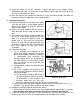
Figure 1A
Diagram showing the arrangement of spark plug wires and top center cover.
Figure 1B
1. Drive belt (alternator)
2. Drive belt (power steering)
3. Tensioner pulley bracket (air conditioner)
4. Drive belt (air conditioner)
5. Pulley (water pump)
6. Pulley (power steering)
7. Pulley (crankshaft)
8. Timing belt cover (upper)
9. Timing belt cover (center)
10. Timing belt cover (lower)
11. Timing belt
12. Tensioner pulley (timing belt)
13. Auto tensioner (timing belt)
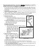
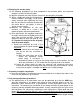
Figure 2A
Diagram showing the relationship of the pulleys when cylinder no. 1 is at TDC on compression.
Figure 2B
Diagram showing the location of the plug on the rear side of the engine block. Secondary
diagram shows the balance shaft in its proper position.
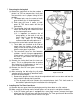
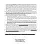
Figure 3A
Diagram showing the proper way to compress the tensioner.
Figure 3B
Diagram showing how the lock-pin is to be inserted into the automatic tensioner.
Figure 3C
Diagram showing how to tension the timing belt during assembly of pulley system.
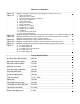
Figure 4
A. 6 x 16mm flange bolts
B. 6 x 18mm flange bolts
C. 6 x 25mm washer assembled bolts
D. 6 x 25mm flange bolts
E. 6 x 45mm flange bolts
Torque Specifications
A/C idler pulley bracket bolts 20 ft-lbs.
Alternator adjustment bolt 10 ft-lbs.
Alternator mounting bolts 17 ft-lbs.
Automatic tensioner 17 ft-lbs.
Cam gear adjustment bolts 15 ft-lbs.
Camshaft pulley bolt 85 ft-lbs.
Crankshaft pulley bolts 18 ft-lbs.
Front cover bolts 7.2~8.7 ft-lbs.
Spark plug 18 ft-lbs.
Timing belt tension pulley 35 ft-lbs.
Timing belt tensioner pre-load 2.6 ft-lbs.
Top center cover bolts 2.2 ft-lbs.
Water pump pulley nuts 8 ft-lbs.