
User manual

Version: 2009-10-09
Installation of the Sensors
When you install the Sensors please regard that the openings for the ventilation shows at the top and to below. If you not regard this, dependent of the install location the
heat could be tailback in the case and so the measured value would be wrong. Also install locations like cold or heat walls or cupboards could affect the measured value.
The divergence of the measured value can be compensated in the configuration menu of the CS121 under “SensorManager”. A divergence of e.g. +3 C° can be
compensated with an offset value of “-3”. The standard calibration values of all our sensors are the follows :
Sensor Type :
SensorManager
Scaling Divisor:
SiteManager II
Sensor Range
SM_T / SM_II_T Temperature sensor
2.55
0 –100 C°
SM_T_Plus / SM_II_T_Plus Temperature sensor
2.55, Offset – 30
-30 – 70 C°
SM_T_H / SM_II_T_H Temp. & Humidity sensor
2.55, 2.55
0 – 100 C°, 0% -100% rel. humidity
SM_T_H_Rev.A / SM_II_T_H_Rev.A Temp. &
Feuchtesensor
2.55, 2.55
0 – 100 C°, 0% -100% rel. Feuchte
SM_II_DIG Temperature sensor
-
-25 – 100 C°
Connecting the sensors
You have the option to connect two sensors (not SM_T_H / SM_II_T_H) on one Port of the SensorManager / SiteManagerII because every Port has two Channels.
You have the following variants :
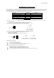
You connect the 2 Sensors (not SM_T_H / SM_II_T_H) serial (Fig.1- Daisy-Chain System).
Here you have to regard that on both Sensor boards the JUMPER must set on PIN 1+2 (Default state).
So the first Sensors is on Channel 1 and the second Sensor is on Channel 2 (Fig.2).
Sensor- oder
SiteManager
Sensor 2
Sensor 1
Fig. 1 Fig. 2: Jumper Channel 1 + 2
You connect the 2 Sensors (not SM_T_H / SM_II_T_H) parallel with the Splitting Plug SPSMRJ (Fig.3).
Here you have to regard that on one Sensor board the JUMPER must set on PIN 2+3.
This Sensor is on Channel 2 (Fig.4).
On the other Sensor board the JUMPER must set on PIN 1+2 (Default state).
This Sensor is on Channel 1 (Fig.5).
Sensor- oder
SiteManager
Sensor 2
Sensor 1
Splitting plug
Fig. 3 Fig. 4: Jumper Channel 1 Fig. 5: Jumper Channel 2
Attachment of the Sensor Housings:
Open the housing at the allocated marking.
Loose the 4 board screws and unplug the board.
Bore holes into the accordant markings and mount the housing with dowels at a wall.
Please note, that the air slits of the sensors will be always exposed.
Please order the article BACS_MNTK for the assembly at top-hat rails.
Mount the clip via counterbore of the bottom panel with the enclosed screw.
Please note, that the lug for the loosening of the top-hat rail will be easy-to-reach.
The drilled hole should not be centrally arranged, but rather deeper accordingly.
Attach the housing via clasping at the top edge of the top-hat rail and press the lug from top to below until the lock.