
User's Manual


--------------------------------------------------------------------------------8/13--------------------------------------------------------------------------------
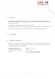
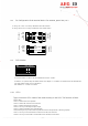
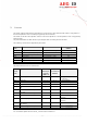
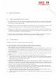
2.8 Pin Configuration of the terminal blocks (for antenna, power lines, etc.)
a) using LiY-LiYCY-Y 2+2x0,5 (delivered until march 2001)
b) using Li2YCY (TP) 3x2x0,34 (delivered from march 2001)
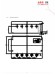
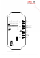
2.9 DIP-Switches
In normal condion (ex work) all DIP-switches are set OFF (down).
If switch 1 is in position ON, the default values (see chapter 3 - firmware) are loaded out of the EPROM at a
cold start (when reader is put in operation).
DIP-switches 2 ... 8 have no function.
2.10 LED´s
There are several LED’s inside of the reader housing on the PCB. The functions of these
LED’s are:
LED 1 on when antenna is operated.
LED 2 on when last read was not successful.
LED 3 on when last read was a success.
LED 4 on as long as the digital input is high.
LED 5 on when a hardware error was detected.
LED 6 flashing as long as the reader is powered and the microprocessor is working properly.
LED 7 on as long as commands were received on the RS 232 interface.
LED 8 on as long as information is transmitted from the RS.232 interface.
On
1 2 3 4 5 6 7 8
DIP-Switch
X1 - reader
antenna
connector
1
2
3
4
5
Data
Schirm
Sync
GND
12V
1
2
6
4
white
shield of white
brown
green
3
shield of brown
5
yellow
X1-reader
antenna
connector
1
2
3
4
5
data
shield
sync
GND
12
V
1
2
6
4
3
5
white
grey
green
yellow
brown
pink
shield