
Installation Guide

--------------------------------------------------------------------------------5/30--------------------------------------------------------------------------------
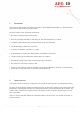
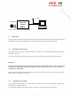
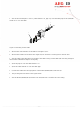
Figure 1: Concept of the reading system
3 Installation
To get the specified reading performance it is necessary to do the installation carefully step by step as it
is described in the following Chapters. All the work must be done by well educated people.
3.1 Mounting of the housing
The reader can be mounted to any other mechanic construction. The distance between reader and tran-
sponder has to tuned
It is recommended to protect the housing against heavy mechanical interactions and drippy fluids.
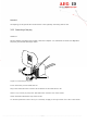
Attention!
The side of the housing showing the antenna symbol must not be brought next to a metal surface. This
could lead to a significant change of the properties of the antenna circuit, which in turn reduces the
reading range considerably.
With the help of the plastic bars, the reader can mounted or screwed on to the most fastening elements
without open the housing of the device.
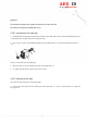
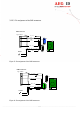
3.2 Grounding of the reader
To get reliable reading results, the reader must be grounded. The connector is placed at the side of the
housing (6.35 mm flat contact).
To avoid EMV-problems, the cable to ground ought to be very short with low impedance.
USB
transponder
reader with
integrated
antenna
ARE i2
9....30V
DC