ADV48 12.
Important Notices 1. Installation of overhead products requires careful planning and preparation. Be extremely careful when working on a vehicle with side curtain air bags. Do not route wires near any portion of the side curtain air bag assemblies. This includes any anchor points in A, B, C or D pillars of the vehicle. Routing wires in these areas or running wires by the side curtain air bags can prevent the side curtain air bag from fully deploying which can result in personal injury to vehicle occupants.
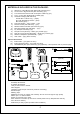
MATERIALS INCLUDED IN THIS PACKAGE: 1) 2) 3) 4) 5) 6) 7) 8) 9) 10) 11) 12) 13) 14) Optional 15) 16) 17) ADV48 TV / Video Monitor with DVD (P/N 136-4423) (1pc) 12 Pin Power / Signal harness (P/N 112-3483) (1pc) 2 Pin Power Wire Harness with choke (P/N 112B3143) (1pc) 9 Pin ~ 3 RCA Jack Pigtail (P/N 112-3682) (1pc) Hardware Package (P/N 150-1674) Screws ISO 3 x 6mm Long – (10pcs) #8 x 3/8" Self Drilling Screws – (4pcs) M5 Screws (4pcs) Trim Ring (Shale) – (1pc), Pewter – (1pc) Remote Control (P/N 136-4427)
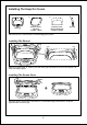
Installing The Snap On Covers 1. 2. 3. Snap On Cover (Shroud) 1 Pewter, 1 Shale Housing 4. Snap On Cover (Screen Back Cab) 1 Pewter, 1 Shale Pry Tool Place the pod on a soft surface to avoid damaging the plastic. Installing The Shroud catch catch (A) Begin by hooking area “A” (above) over the dome light and slide the cover over the pod. The cover will snap in place. Installing The Screen Cover (B) (B) Open the screen and hook the two tabs “B” on the bottom edge of the screen.
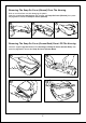
Removing The Snap On Cover (Shroud) From The Housing Work on a soft surface to avoid damaging the plastic. Insert the supplied pry tool between the Housing and Snap On Cover (Shroud), then press the pry tool to release the Snap On Cover (Shroud). 1 2 3 Removing The Snap On Cover (Screen Back) From LCD The Housing Insert the supplied pry tool between the Housing and Snap On Cover (Screen Back), then press the pry tool to release the Snap On Cover (Screen Back).
GENERAL INSTALLATION APPROACH: 1) Decide upon system configuration and options that will be installed (i.e.: what components, VCP, Video Game, external amp, wireless headphones, VCP, etc.). 2) Review all manuals to become familiar with electrical requirements and hook ups. 3) Decide upon mounting locations of all components and method of mounting.
VEHICLE PREPARATION: 1) Locate an accessory power source (+12v when key is in the ACC. and run positions, and 0v when key is off), and also a good ground generally, these wires can be found at the ignition switch or fuse-box. 2) The mounting method and location will vary from vehicle to vehicle, so this manual will only focus on the installation of the ADV48 and related console accessories. 3) Generally, the best location for the video monitor is where the vehicle's factory dome light is installed.
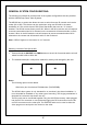
GENERAL SYSTEM CONFIGURATIONS: The following is intended to provide some of the system configurations that are possible with the ADV48 Drop Down Video Systems: The ADV48 has an option that allows the user to select from two IR transmit and receive codes (M1 or M2). This feature can be used when using two ADV48s in the same installation or if the vehicle has an RSA (Rear Seat Audio) that uses an “A” channel headset. The ADV48 comes factory set to M1.
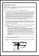
TRIM RING INSTALLATION: Note: This page only covers special installation considerations for thick trim ring installation. If the video monitor is to be installed in a vehicle with the thick trim ring, it may need to be trimmed to fit the contour of the vehicle Head liner. Note: The trim rings supplied with this unit are not designed to be trimmed. 1) In this installation, the video monitor is mounted directly to the overhead cross-member in the roof using the mounting screw bosses.
MOUNTING THE TRIM RING Roof Roof Support Headliner Mounting Bracket Self-drilling Screws Trim Ring Video Unit M5 Screw 10
ADV48 1) Make the connections to the vehicle for the 12 pin wiring harness. 2) Connect power harness to vehicle’s electrical system by tapping into an accessory hot line and a good ground. 3) Connect the 12 pin harness to the mating connector on the Video Monitor. 4) If an auxiliary video input is used (VCP, DVD, etc) insert the Circular Mini-Din Connector of the source component harness through the wire tie loop on the main PCB and into the Mini-Din Connector on the main PCB.
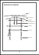
ADV48 VIDEO 2 9 Pin ~ 3 RCA Jack Pigtail * Optional Relay Box SIRSWB PODTVT2 * Antenna for Wireless FM Mod. ** See Antenna Note on the previous page DIN 1 VIDEO 1 12 Pin Power / Signal harness or Accessory Harness - Optional (P/N:8010730) *IPOD HARD WIRE CABLE (Optional) Red RCA (Audio Right) White RCA (Audio Left) Yellow RCA (Video) Power Connector 4 Pin Clean the IR Receiver Window on the front of the VCP.
CONNECTING THE DOME LIGHTS The dome lights in the video monitor require three connections to the vehicle's wiring. There are two common types of dome light circuits used, positive or negative switched. Positive systems supply voltage to the interior lights to turn them on, negative switched systems apply ground to illuminate the bulbs. To determine which system you have you must locate the wires at the dome light.
Negative Switched Dome Lighting To 12 pin connector Red / black - Lamp on Black / red - Lamp common Purple / brown - Lamp Auto To constant To constant Factory Door ajar switch or Body Control computer Troubleshooting: SYMPTOM: REMEDY: No power at Video Monitor Verify +12 VDC on Red wire at 2 pin Power Harness behind video monitor.
, , For Customer SelVlce Visit Our Website At www.audioYOLCOm Product Infonnation. Photos. FAQ's Owner's Manuals © 2007 Audiovox Electronics Corp. 150 Marcus Blvd.