ADV10A 10.
Important Notice An LCD panel and/or video monitor may be installed in a motor vehicle and visible to the driver if the LCD panel or video monitor is used for vehicle information, system control, rear or side observation or navigation. If the LCD panel or video monitor is used for television reception, video or DVD play, the LCD panel or video monitor must be installed so that these features will only function when the vehicle is in "park" or when the vehicle,s parking brake is applied.
MATERIALS INCLUDED IN THIS PACKAGE: 1) 10.
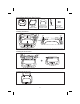
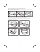
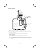
Installing the Snap On Covers 1. Housing 2. 3. 4. Snap On Cover (Shroud) 1 Pewter, 1 Shale Snap On Cover (Screen Back Cab) 1 Pewter, 1 Shale Pry Tool 5. Screw Cap (L & R) 2 Pewter, 2 Shale Place the unit on a soft surface to avoid damaging the plastic. Installing The Shroud catch catch Remove tape backing before installing. (A) Begin by hooking area “A” (above) over the dome light and slide the cover over the unit. The cover will snap in place.
Removing the Snap On Cover (Shroud) from the Housing Work on a soft surface to avoid damaging the plastic. Insert the supplied pry tool between the Housing and Snap On Cover (Shroud), then press the pry tool to release the Snap On Cover (Shroud). 1 2 3 Removing the Snap On Cover (Screen Back) from the LCD Housing Insert the supplied pry tool between the Housing and Snap On Cover (Screen Back), then press the pry tool to release the Snap On Cover (Screen Back).
GENERAL INSTALLATION APPROACH: 1) Decide upon system configuration and options that will be installed (i.e.: what components, Video Game, external amp, wireless headphones, VCP, etc.). 2) Review all manuals to become familiar with electrical requirements and hook ups. 3) Decide upon mounting locations of all components and method of mounting.
GENERAL SYSTEM CONFIGURATIONS: The following is intended to provide some of the system configurations that are possible with the ADV10A Drop Down Video Systems: The ADV10A has an option that allows the user to select from two IR transmit and receive codes (M1 or M2). This feature can be used when using two ADV10As in the same installation or if the vehicle has an RSA (Rear Seat Audio) that uses an “A” channel headset. The ADV10A comes factory set to M1.
TRIM RING INSTALLATION: Note: This page only covers special installation considerations for thick trim ring installation. If the video monitor is to be installed in a vehicle with the thick trim ring, it may need to be trimmed to fit the contour of the vehicle Headliner. Note: The trim rings supplied with this unit are not designed to be trimmed. 1) In this installation, the video monitor is mounted directly to the overhead cross-member in the roof using the mounting screw bosses.
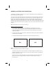
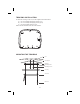
TRIM RING INSTALLATION: To install the Trim Ring to the unit, use the supplied screws listed below: A) #4 x 5/16 Phillips Self Tapping Screws (1 pc) B) #4 x 7/16 Phillips Self Tapping Screws (3 pcs) C) M3 x 8mm Phillips Screws (5 pcs) Please see the illustration below for screw locations.
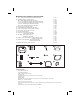
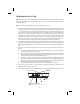
WIRING DIAGRAM Dome Light Power source Line In-V (Yellow) Line Out-V (Yellow) Line In-L (White) Line In-R (Red) 10 Pin A/V In Out Harness Dome Light Extension Harness (P/N 112-3884) Power Supply Harness Line Out-L (White) Line Out-R (Red) 2 Pin Power Harness (P/N 112-4152) * Antenna for Wireless FM Mod. ** See Antenna Note 1) Make the connections to the vehicle for the 10 pin wiring harness.
CONNECTING THE DOME LIGHTS The dome lights in the video monitor require three connections to the vehicle's wiring. There are two common types of dome light circuits used, positive switched systems or negative switched systems. Positive switched systems supply voltage to the interior lights to turn on; negative switched systems apply ground to illuminate the bulbs.
Negative Switched Dome Lighting To 3 pin connector Red / black - Lamp on Black / red - Lamp common Purple / brown - Lamp Auto To constant +12 VDC Fused To constant +12 VDC Factory Door ajar switch or Body Control computer Troubleshooting: SYMPTOM: REMEDY: No power at Video Monitor Verify +12 VDC on the Red wire at 2 Pin Power Harness behind the video monitor. Verify a ground connection with a continuity test from a known good ground to the black wire at the 2 Pin Power Harness.