
User manual


Table Of Contents
- Contents
- Chapter 1 Introduction
- Chapter 2 Installation
- 2.1 Jumpers
- 2.2 Connectors
- 2.3 Locating jumpers and Connectors
- 2.4 Setting Jumpers
- 2.5 Clear CMOS (JP2)
- 2.6 Installing DIMMs
- 2.7 IDE, CDROM hard drive connector (CN18)
- 2.8 Solid State Disk
- 2.9 Parallel port connector (CN17)
- 2.10 Keyboard and PS/2 mouse connector (CN15)
- 2.11 Front Panel Connector (CN5)
- 2.12 Power connectors (CN11,CN1)
- 2.13 Power ON/OFF switch con. pin 11-12 of CN5
- 2.14 Audio AC'97 Link interfaces (CN21)
- 2.15 COM port connector (CN19)
- 2.16 VGA/LVDS interface connections (CN26, CN22)
- 2.17 TV-out interface
- 2.18 Ethernet configuration (CN6, CN10)
- 2.19 USB connectors (CN12,CN13,CN14)
- 2.20 LCD Backlight connector (CN23)
- 2.21 SATA Connector (CN7, CN9)
- 2.22 DI/O connector (CN16)
- 2.23 CPU Fan power supply connector (CN11)
- Chapter 3 Software Configuration
- Chapter 4 Award BIOS Setup
- 4.1 System test and initialization
- 4.2 Award BIOS setup
- 4.2.1 Entering setup
- 4.2.2 Standard CMOS Features setup
- 4.2.3 Advanced BIOS Features setup
- 4.2.4 Advanced Chipset Features setup
- 4.2.5 Integrated Peripherals
- 4.2.6 Power Management Setup
- 4.2.7 PnP/PCI Configurations
- 4.2.8 PC Health Status
- 4.2.9 Frequency/Voltage Control
- 4.2.10 Load Optimized Defaults
- 4.2.11 Set Password
- 4.2.12 Save & Exit Setup
- 4.2.13 Exit Without Saving
- Chapter 5 PCI Graphic Setup
- Chapter 6 Audio Setup
- Chapter 7 LAN Configuration
- Appendix A Prog. GPIO & W’dog Timer
- A.1 Supported GPIO Register
- A.2 Watchdog programming
- Table B.1: CN1 Power Connector
- Table B.2: CN2 LAN LED
- Table B.3: CN4 PCI -5V & -12V Input
- Table B.4: CN5 SYSTEM PANEL
- Table B.5: CN6 LAN1 CONNECTOR
- Table B.6: CN7 SATA2 connector
- Table B.7: CN9 SATA1 connector
- Table B.8: CN10 LAN2 CONNECTOR
- Table B.9: CN11 CPU FAN connector
- Table B.10: CN12 USB5/6 connector
- Table B.11: CN13 USB3/4 connector
- Table B.12: CN14 USB1/2 connector
- Table B.13: CN15 KB/MS
- Table B.14: CN16 GPIO
- Table B.15: CN17 Print Port connector
- Table B.16: CN18 IDE connector
- Table B.17: CN19 COM1/2/3/4 connector
- Table B.18: CN20 PC104+ Connector
- Table B.19: CN21 AUDIO connector
- Table B.20: CN22 LVDS Connector
- Table B.21: CN23 LCD Backlight
- Table B.22: CN24 CD_IN connector
- Table B.23: CN25 48bit LVDS Connector
- Table B.24: CN26 CRT connector
- Table B.25: CN27 SYS FAN connector
- Table B.26: CN28 Inverter connector
- Table B.27: CN29 SPK-OUT connector
- Table B.28: CN30 Compack II W/Ejector
- Table B.29: CN31 MINI PCI connector
- Table B.30: CN32 MIO USB connector
- Appendix C System Assignments
- Appendix D Optional Extras
- Appendix E Mechanical Drawings
- Appendix F AT/ATX Power setting
15 Chapter 2
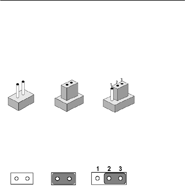
2.4 Setting Jumpers
You may configure your card to match the needs of your application by
setting jumpers. A jumper is a metal bridge used to close an electric cir-
cuit. It consists of two metal pins and a small metal clip (often protected
by a plastic cover) that slides over the pins to connect them. To “close” a
jumper, you connect the pins with the clip. To “open” a jumper, you
remove the clip. Sometimes a jumper will have three pins, labeled 1, 2
and 3. In this case you would connect either pins 1 and 2, or 2 and 3.
The jumper settings are schematically depicted in this manual as follows:.
A pair of needle-nose pliers may be helpful when working with jumpers.
If you have any doubts about the best hardware configuration for your
application, contact your local distributor or sales representative before
you make any changes.
Generally, you simply need a standard cable to make most connections.
open closed closed 2-3
open closed closed 2-3